Products
PI Is a Worldwide Leading Supplier of Solutions in the Fields of Motion and Positioning
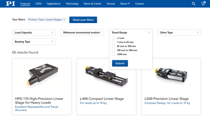
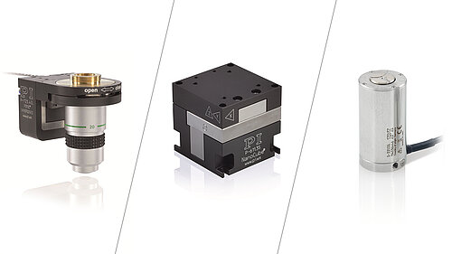
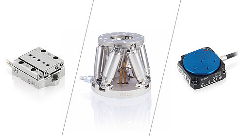
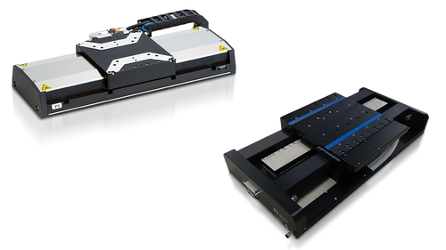
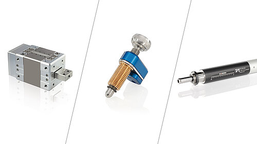
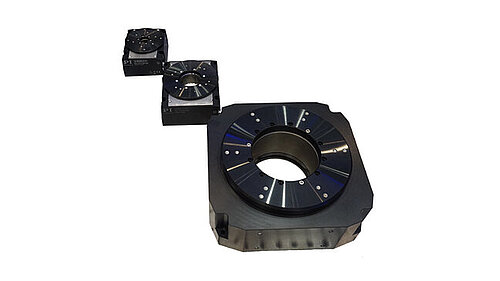
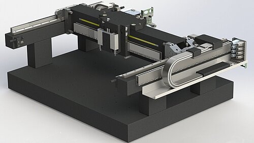
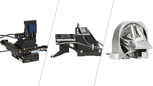
PI does not only develop and produce a broad range of positioning stages and actuators for linear, rotary and vertical motion or combinations of different axes. PI also adapts those solutions to customer-specific applications or supplies finished subsystems for motion and positioning.
The control is an important system component and is also supplied by PI. This not only provides sophisticated control concepts but also the hardware and software interfaces for the application environment.
Whether a standard product or a completely new development, whether OEM drive or an integrated system, the objective is always to provide the optimum solution for every possible application.