Glad you are here!
In our digital event "Let's Shape the Future of Laser Materials Processing", we want to bring together the knowledge and trends of the business sector in order to make use of the potential of the laser as a tool and to jointly shape the future of materials processing. You can expect exciting presentations from experts on the latest market developments, applications, and technologies. Let yourself be inspired and enthused.
All persons involved in the event were tested negative for Covid-19 in advance. Are you having problems watching the recording? Then click here.
Agenda
| Welcome to the It’s Possible Sessions! | |
| Keynote: Markus Spanner, CEO PI | |
| Keynote: Dr. Dirk Müller, Director of Strategic Marketing Coherent | |
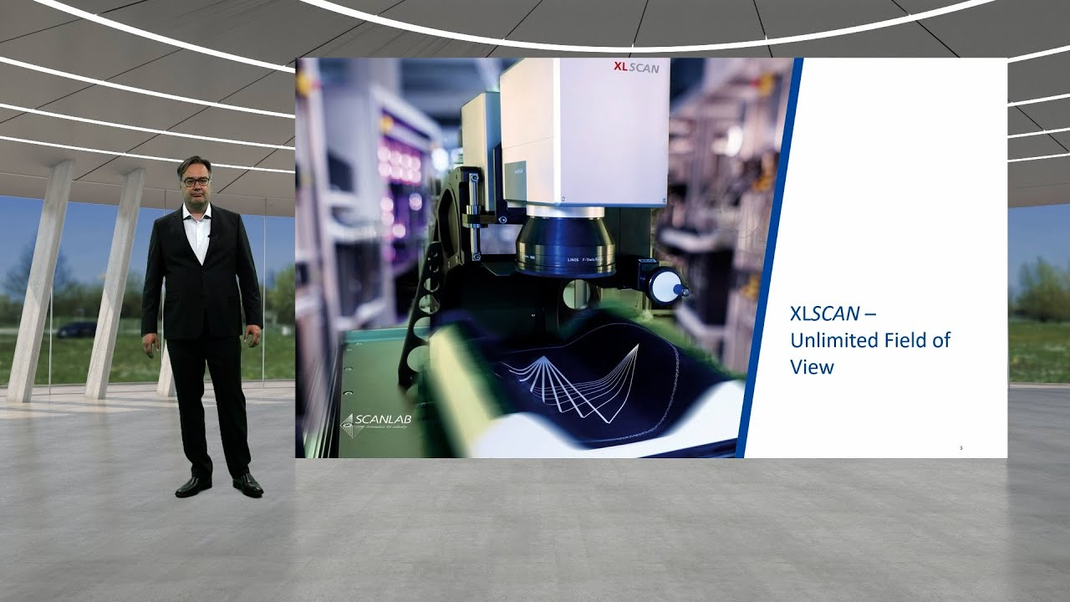
| Session 1: Addressing Extremely High Feature Density and Throughput Requirements in Electronics Manufacturing Increasing Accuracy and Throughput by Using Multibeam Galvo Scanners (Dr. Holger Schlüter, SCANLAB) Enhancing Laser Processing in Electronics Manufacturing by Using CAD-CAM Software (Sarunas Vaskelis, DMC) | |
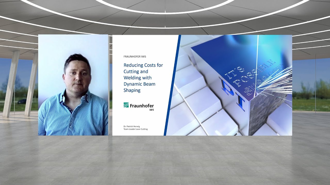
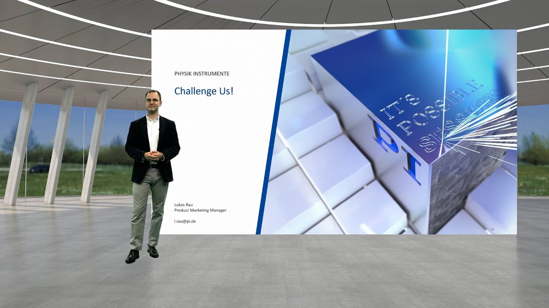
| Session 2: Improving Efficiency in Macro Laser Materials Processing with Piezo Actuation Reducing Cost for Cutting and Welding with Dynamic Beam Shaping (Dr. Patrick Herwig, Fraunhofer IWS) Piezo Components for Efficient Dynamic Beam Manipulation (Lukas Rau, PI) | |
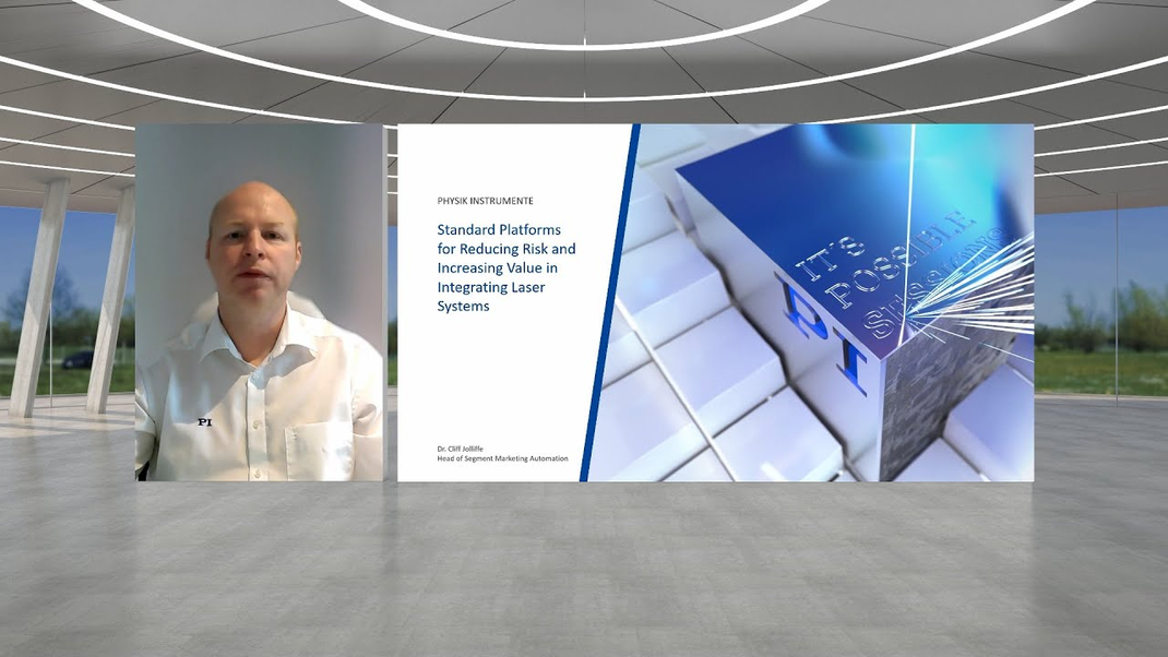
| Session 3: Unlocking the Potential of Laser Processing with Precision Laser Machine Concepts The Use of High-Precision Laser-Assisted Additive Manufacturing for Advanced Tissue Engineering (Dr. Ulf Hinze, Laser nanoFab) Standard Platforms for Reducing Risk and Increasing Value in Integrating Laser Systems (Dr. Cliff Jolliffe, PI) | |
| It’s Possible Conclusion & Goodbye |

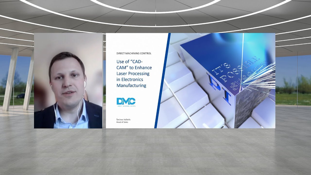
The technology to put electrical contacts on the plastic part was developed by the Center for Physical Sciences and Technology in Lithuania and DMC software was used to make the actual part using the 5 axes setup. It is a promising technology, allowing to deposit metal tracks on a very wide range of surfaces much cheaper than it is done currently.
This question could not be answered by a fix value. This depends on the weight of different optimization targets, the sheet thickness, and the used laser beam. If you want to enlarge the cut kerf width to enable automation of unloading the machine, we have to enlarge the perpendicular amplitude. All in all the XY oscillation should be in a range between factor 1 to 3 of the focus diameter. In case of Z the amplitude should achieve a virtual Rayleigh length of sheet thickness to cut minus the real wavelength. For example, the used laser beam has a Rayleigh length of 3 mm. For cutting 10 mm thick sheets, an amplitude of 4 mm is useful (2*3mm + 4 mm = 10 mm).
Additional costs has to be answered by PI. I can say something about the savings. If we talk about a process speed, an increase of 50% is possible. That means we can cut 50% more by same running costs.
The running costs consist of energy (3-5 € per hour saving 1.5-2 € per hour). For fusion cutting we use compressed nitrogen. Thick sheet needs up to 2m³/min 120 m³/h. The m³ nitrogen cost 15 ct. If we can save 50% gas, a saving of up to 9 € is possible. I expect a reduction of running costs between 5 and 10 € per hour for thick sheet fusion cutting.
Further additional effort for dross removal could be saved.
The lifetime of the melt pool gets enlarged. The gas, which was "stored" during casting process transforms in the melt pool to small bubbles. The longer lifetime gives the bubbles more time for flooding and avoids to be caught in the weld seam. Further, the bubbles get steered out of the process zone. The chief uses a spoon, we use the laser beam. This supports the flooding, too.
Effective cooling of the piezo actuator needs direct contact of the cooling medium with the whole actuator stack, the piezo needs to "swim" in the cooling medium. Therefore, water ist no option. If any, then oil (a medium which is also not available at the system). On top: Incompressible oil might affect the dynamic performance.
The piezo tip/tilt mirror platform is a two axis system with only one mirror. This allows for much smaller form factors compared to a galvo scanner (only ~ 1/8th of integration space). On the other hand, the piezo tip/tilt has a much smaller angular travel range, yet this disadvantage can be neglected due to the small travel range needed for dynamic beam oscillation.
Comparative tests in cutting performance tests at the Fraunhofer IWS showed no difference in the observed process window, but you still have the advantage of a small integration space.
It is a question of design. The systems have been developed for 90° angled cutting heads, this means 45° angle of incidence. The coatings have been optimized for this angle. But they can be changed, if needed.
Maximum laser power is also a design question, taking the reflectivity of the optical element into account.
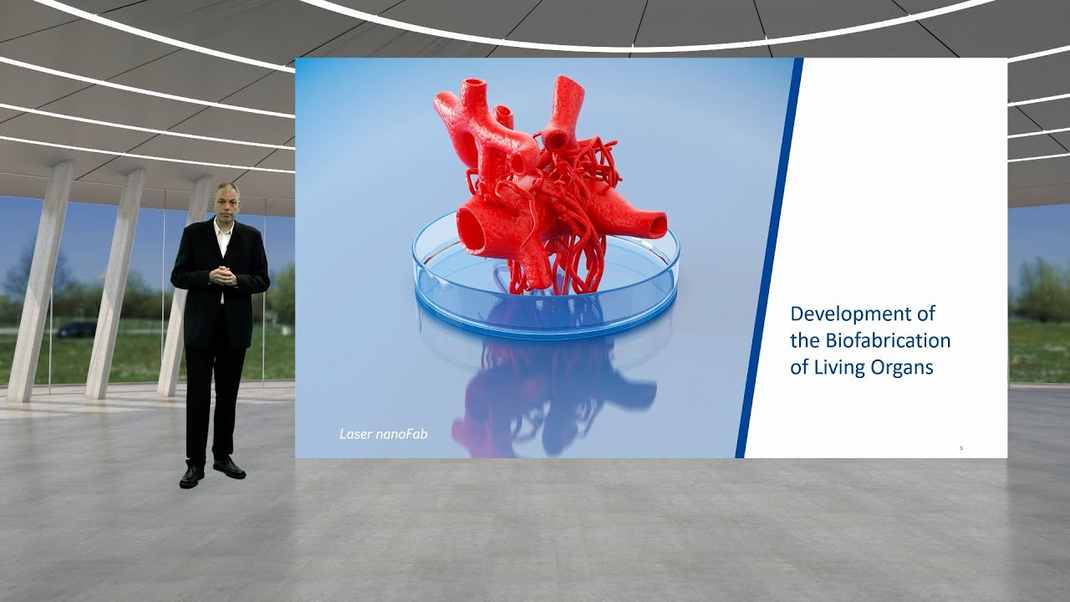
This depends on the desired resolution. In principle, almost any number of cells could be printed at once by increasing the size of the transferred droplet. However, more than 1000 cells per droplet is usually not practical for tissue engineering and some applications require that only a few cells per droplet be printed. It must be taken into account that the speed at which printing can be performed is directly dependent on the resolution.
Different cell types take on very different forms in their respective tissues. Some are rather compact, keratinocytes for example, while others, such as neuronal cells, have long extensions; the tissue structures they form also differ significantly. The structure of the scaffolds should be adapted to the needs of the particular cell type so that they can grow optimally and cross-link to form tissue. Our scaffolds are computer designed and laser fabricated so that their 3D geometry can be completely defined. We can optimally adapt the scaffold geometry to the respective cell type.
Basically, you have to distinguish between the pure printing time and the time for the entire process. Of course, the cells have to be grown over several weeks or months. When printing an organ, these would then have to be dissociated and made available in time. After that, a more or less automated material feed would still significantly affect the overall time. It would be crucial to be finished with the entire process before cells die due to inadequate supply after several hours; however, this time span can be extended biochemically.
The pure printing time can be estimated as follows: A 100-kHz laser and 10 cells per droplet can print one million cells per second, or 3.6 billion cells per hour. Since the laser repetition rate can also be higher, and the average cell count per droplet could probably be slightly higher than ten for many organs, this number could be even higher; especially if more than one print head is used.
For organs, total cell counts are reported to be in the single or double-digit billions, so that would translate to a few hours of pure printing time. This is a simple estimate and currently not feasible, but it shows that with further optimization and automation, printing entire organs is not unrealistic in the future.
The XL Scan technology is definitely a very interesting technology. Already today, the size of our scaffolds is limited less by the positioning technology itself than by the printing time and the XL Scan technology offers an attractive opportunity to make the process even faster and more technically intelligent.
No, the motion trajectory generation occurs on the motion controller whose internal processor does the processing. This avoids the need to install a real-time extension or special software on the PC, which can problematic due to windows software updates and may require a strict control of the PC hardware or windows updates.
For the use of the SPC CAD/CAM software, if the job involves intricate 3D detail, then a faster PC may be required to reduce the process time for converting the drawing to a motion profile.
Accuracy is the combination of the stages and galvo, so choose a good scanner. There are new models that are offering single digital micron performance and much better thermal properties.
Ensure that the stage and the galvo fields are aligned, by ensuring that field size and alignment are matched.
There are tools available to automate this process in the SPC CAD/CAM software.
The reference for the system accuracy is normally the stage, so having a stage system is good quality is very important.
You could use a smaller scanner field of view if the process throughput allows, this would also reduce the effect of yaw in the stages as this can not be mapped out in terms of field rotation, and the error increases from the stage carriage center.