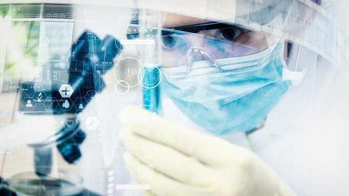
How is Fluorescent Microscopy Used?
Fluorescent microscopy is especially useful for cytodiagnostics ─ the microscopic examination of cells in body tissue or fluids ─ and provides insights into fundamental research, for example, the origin of disease. Fluorescent microscopes are also used to localize inflammation or cancer cells in the body, detection of bacteria or pharmaceuticals in the tissue or even for identifying genetic damage in sperm.
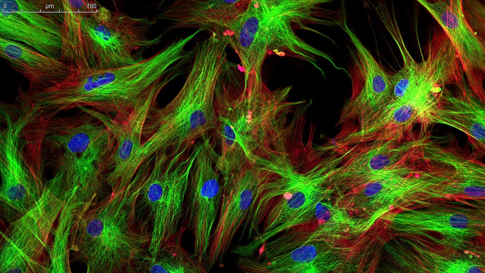
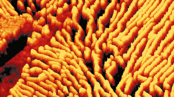
Fascinating Insights Thanks to the Fluorescent Microscope
How can Setup and Adjustment be Successful?
The answer comes from >> GATTAscope project, carried out by GATTAquant in cooperation with various partners. Tutorials and various tips & tricks explain the setup and use of microscopy systems using the example of a modular GATTAscope. After setting up the microscope, nanorulers are used to check the resolution and accuracy of the microscopic image. If the microscope provides the expected results, system errors can be ruled out.
To realize the project, GATTAquant selected various partners to achieve optimum setup ─ PI is one of them and provided several components!
Adjusting the Laser's Angle of Incidence
This is How it's Done!
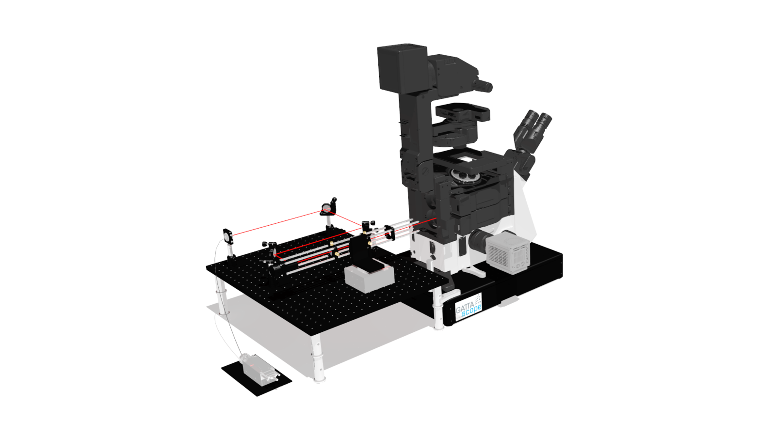
The GATTAscope uses the TIRFM process (total internal reflection fluorescence microscopy). To achieve total reflection, the laser beam does not hit the sample to be examined orthogonally, but at a flat angle. Therefore, the laser beam does not penetrate deeply into the sample, but instead only stimulates fluorescence of the molecules on the surface. The resulting image has a much higher contrast than an image produced by classical fluorescence microscopy.
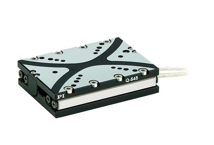
A radiation cage with mirror and lenses is moved vertically to set the critical angle required in the GATTAscope, so the beam does not go through the center of the lens but is deflected to the edge at a certain angle. Total reflection is achieved when the critical angle is reached exactly. Two >> Q-545 Q-Motion® precision linear drives take care of this job. Thanks to their piezoelectric inertia principle, they provide high nanometer-accurate position resolution, are compact and on top of that, inexpensive. Control is done by the >> E-872.401 Q-Motion® driver electronics.
Meaningful Images Thanks to High-Precision Positioning of the Sample
First of all, the PILine® stage positions the sample on the plane quickly and exactly to the micrometer, controlled by a >> C-867 PILine® motion controller.
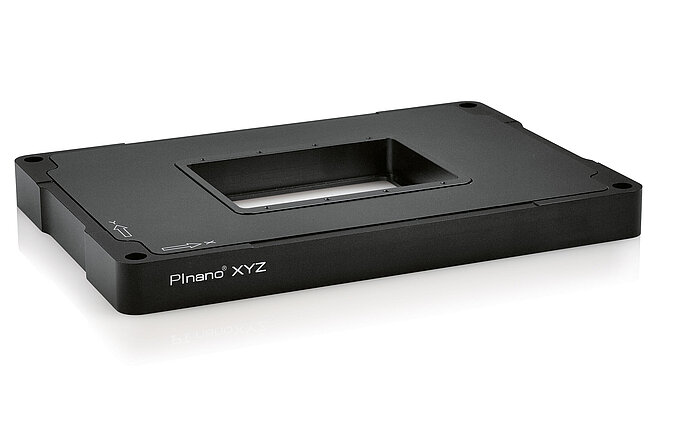
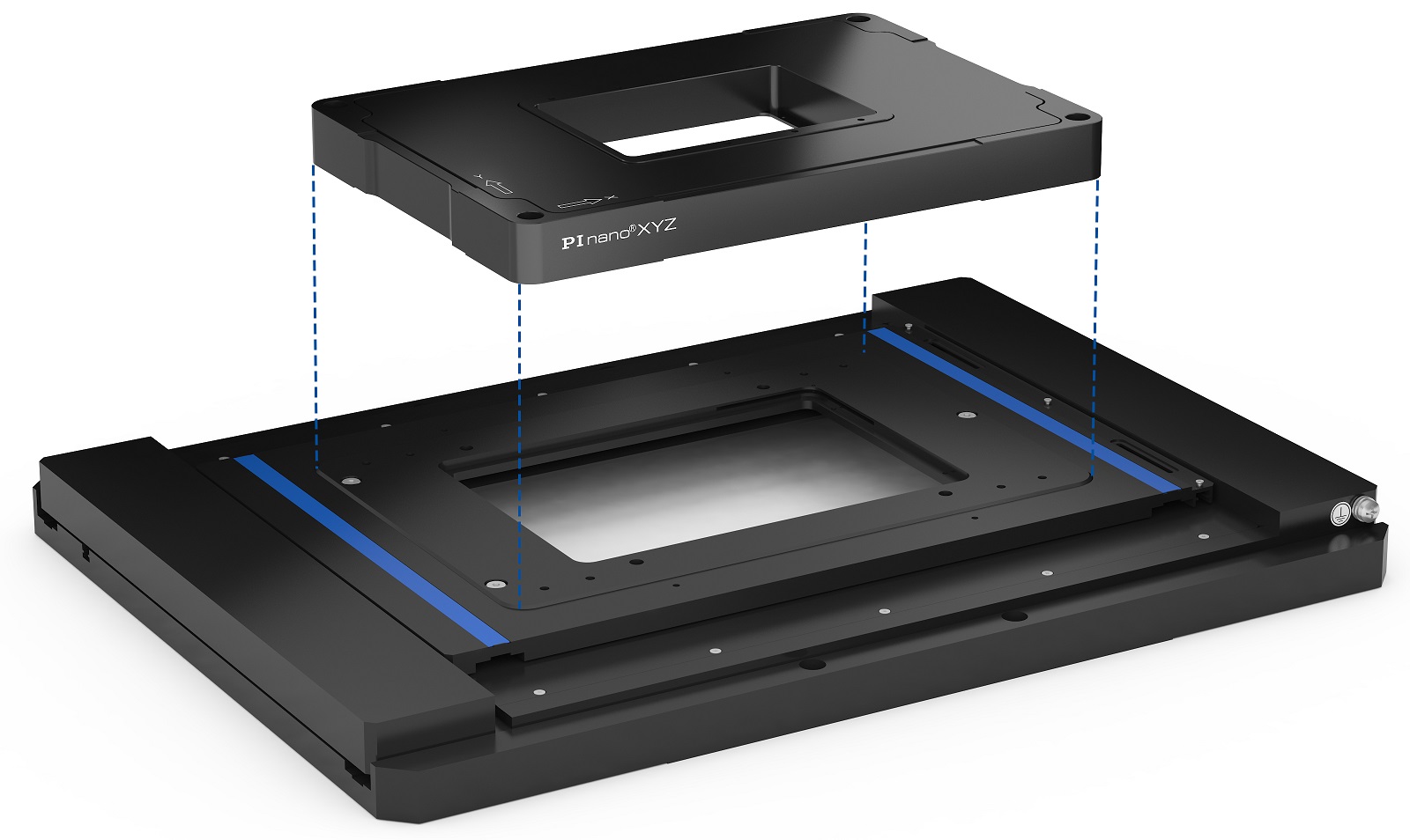
A very low-profile high-precision PInano® XYZ piezo system is mounted in a PILine® stage, the >> P-545.3R8S. In order to produce in-depth insights and revealing images, it scans the entire sample in nanometer steps in the X and Y direction. Extremely fine motion allows 3-D measurements to be made in the Z direction and this realizes the associated shift in focus.
In addition, the PInano® offers low-noise positioning with a very fast and reliable >> E-727 controller.
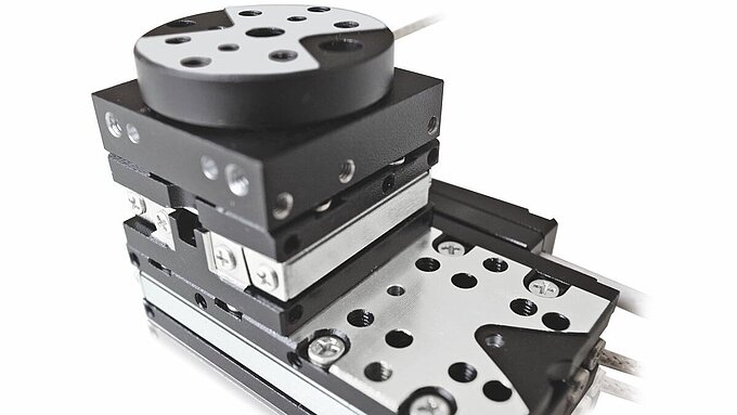
What's in the PILine® Stage?
The outstanding feature of the PILine® ultrasonic drive is its high velocity up to 500 mm/s, which allows rapid positioning to resolution 2 nm. When switched off, the self-locking drive holds the position of the stage mechanically stable. Energy consumption and heat generation are therefore low.
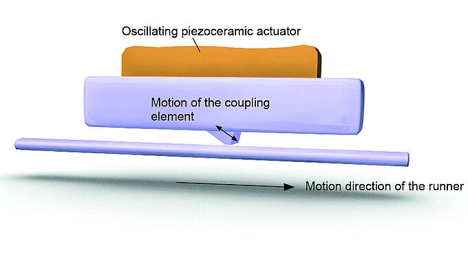
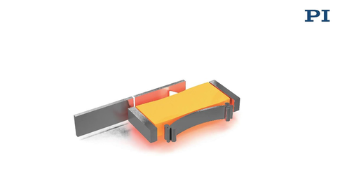
The highlight is the unique drive principle:
A piezo actuator is preloaded against movable a guidable runner via a coupling element and a high-frequency AC voltage is applied to stimulate ultrasonic oscillation between 100 and 200 kHz. This causes the actuator to change its shape and the coupling element pushes the runner forwards or backwards by a few nanometers. Rapid repetition of this motion leads to the high velocities of the PILine® drives.