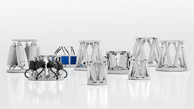
Compact Design, no Trailed Masses or Cables
Compact Design, no Trailed Masses or Cables
In a parallel-kinematic, multi-axis system, all actuators act directly on a single moving platform. This means that all axes can be designed with identical dynamic properties, thus reducing the moved mass considerably. Additional advantages: The parallel-kinematic system can be designed more compact as serial stacked or nested systems. The errors and masses of the individual axes are not cumulated. Parallel-kinematic systems are available with up to 6 levels of freedom and offer high dynamics over all axes due to minimal mass inertia.
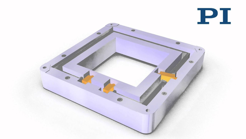
Parallel Metrology: Multi-Axis Measurements Using a Fixed Reference
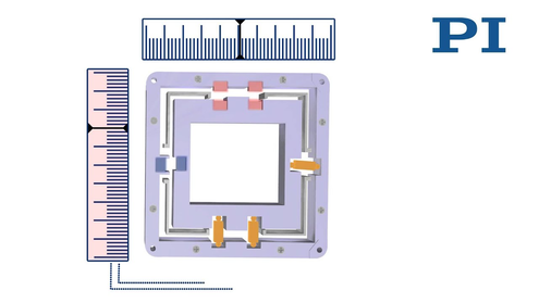
Parallel Metrology: Multi-Axis Measurements Using a Fixed Reference
A multi-axis stage design with parallel kinematics allows the use of direct parallel metrology, measuring all degrees of freedom of the moving platform in relation to a fixed reference. Unintended crosstalk of the motion into a different axis, e.g., as a result of force, can thus be detected and actively corrected in real time. This active guiding allows high trajectory fidelity in the nanometer range, even at dynamic operation.
Kinematics of Multi-Axis Tip/Tilt Systems

Piezo tip/tilt mirror systems from PI are based on parallel kinematics with a single movable platform for all directions of motion. The systems achieve a higher linearity than can be attained by switching two single-axis systems in succession, – e.g., as is the case with galvanoscanners – whilst remaining extremely compact.
Piezo-actuated tip/tilt mirrors and platforms are suitable both for highly dynamic operation, such as tracking, scanning, image stabilization, elimination of drift, and vibration, as well as for static positioning of optical systems and specimens. They allow for an optical beam deflection up to 100 mrad, extremely short response times of a few microseconds and resolutions down to the nanoradian range. PI offers a large range of compact systems for laser beam control up to large units used for astronomy.
Tip/Tilt System with Tripod Piezo Drive
The platform is driven by three piezo actuators that are located in 120° angles to one another. By means of coordinate transformation, the motion can be split among the different actuators.
In addition to tilting, the platform can also be used linearly in Z direction, which is important, for example, for correcting optical path lengths (phase shifters).
The following equations serve to calculate the tilt angle and the travel range in Z. A, B and C are the linear displacement of the corresponding actuators:
Tip/Tilt System with Differential Piezo Drive (Tetrapod)
Tip/Tilt System with Differential Piezo Drive (Tetrapod)
The platform is driven by two pairs of piezo actuators located at 90° angles to one another. The four actuators are controlled differentially in pairs, depending on the tilt direction. As the tilt axes θX and θY are arranged orthogonally, a coordinate transformation is not necessary.
The result is excellent position/angle stability over a large temperature range. Same as for the tripod design, the differential version guarantees optimum angular stability over a large temperature range. For position controlled versions, the differential evaluation of two sensors per axis provides improved linearity and resolution.


Dynamics of a Piezo Tip/Tilt Mirror
The maximum operating frequency of a piezo tilt system strongly depends on its mechanical resonant frequency. The properties of amplifier, controller and sensor are also of considerable importance. To estimate the effective resonant frequency of the system - a combination of platform and mirror - it is necessary to calculate the moment of inertia of the mirror substrate first.


The resonant frequency of the platform (see >> Product Specifications) and the moment of inertia of the mirror substrate give the system's resonant frequency according to the following equation: