A-110.050A1
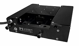
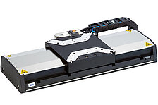
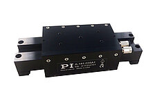
PIglide LC linear stage, air bearings, 50 mm travel range, incremental linear encoder with sin/cos signal transmission, 20 µm sensor signal period, ironless 3-phase linear motor, 48 V
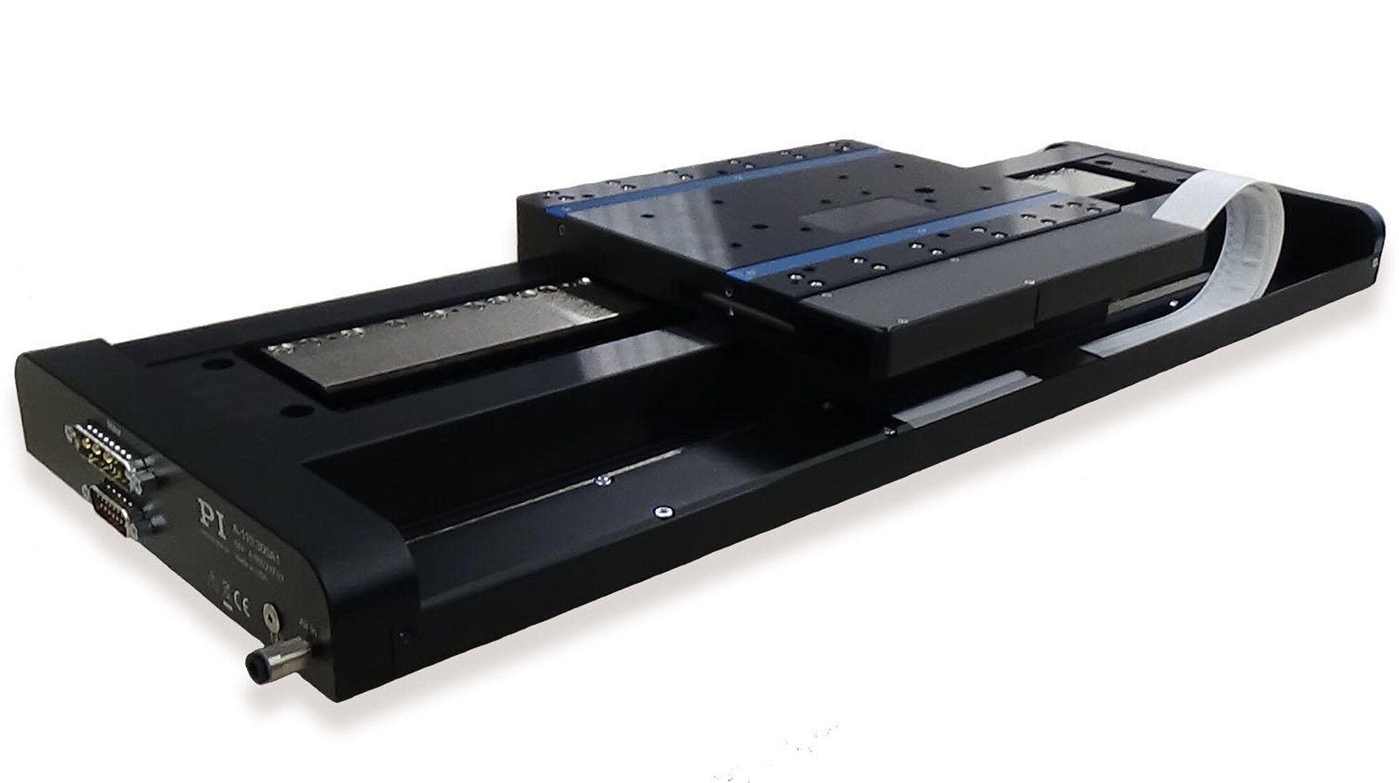


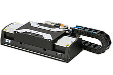
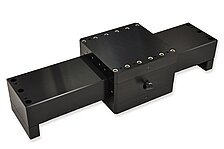
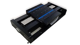
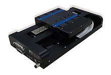
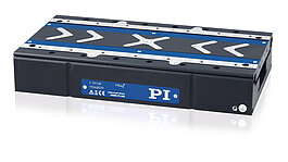
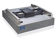
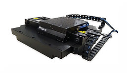
PIglide positioning systems have a magnetic linear motor, magnetically preloaded air bearings and an optical linear encoder: Noncontact and friction-free motion for the highest accuracy and reliability
PIglide positioning systems are ideally suited for many high-precision applications such as metrology, photonics, and precision scanning in semiconductor or flat panel display manufacturing.
Thanks to the friction-free motion, no particles are formed, which makes PIglide stages ideal for cleanroom applications.
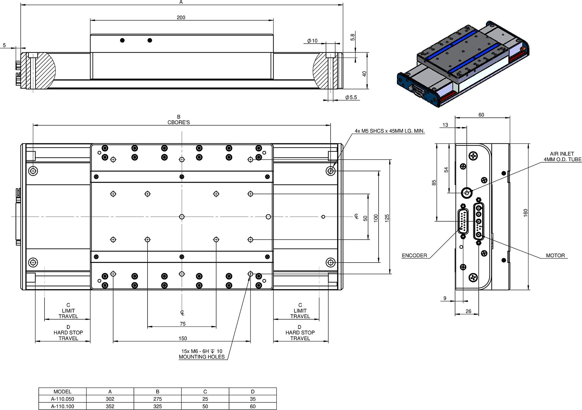
| Motion | A-110.050A1 | A-110.050B1 | A-110.100A1 | A-110.100B1 | A-110.200A1 | A-110.200B1 | A-110.300A1 | A-110.300B1 | A-110.400A1 | A-110.400B1 | Tolerance |
|---|---|---|---|---|---|---|---|---|---|---|---|
| Active axes | X | X | X | X | X | X | X | X | X | X | |
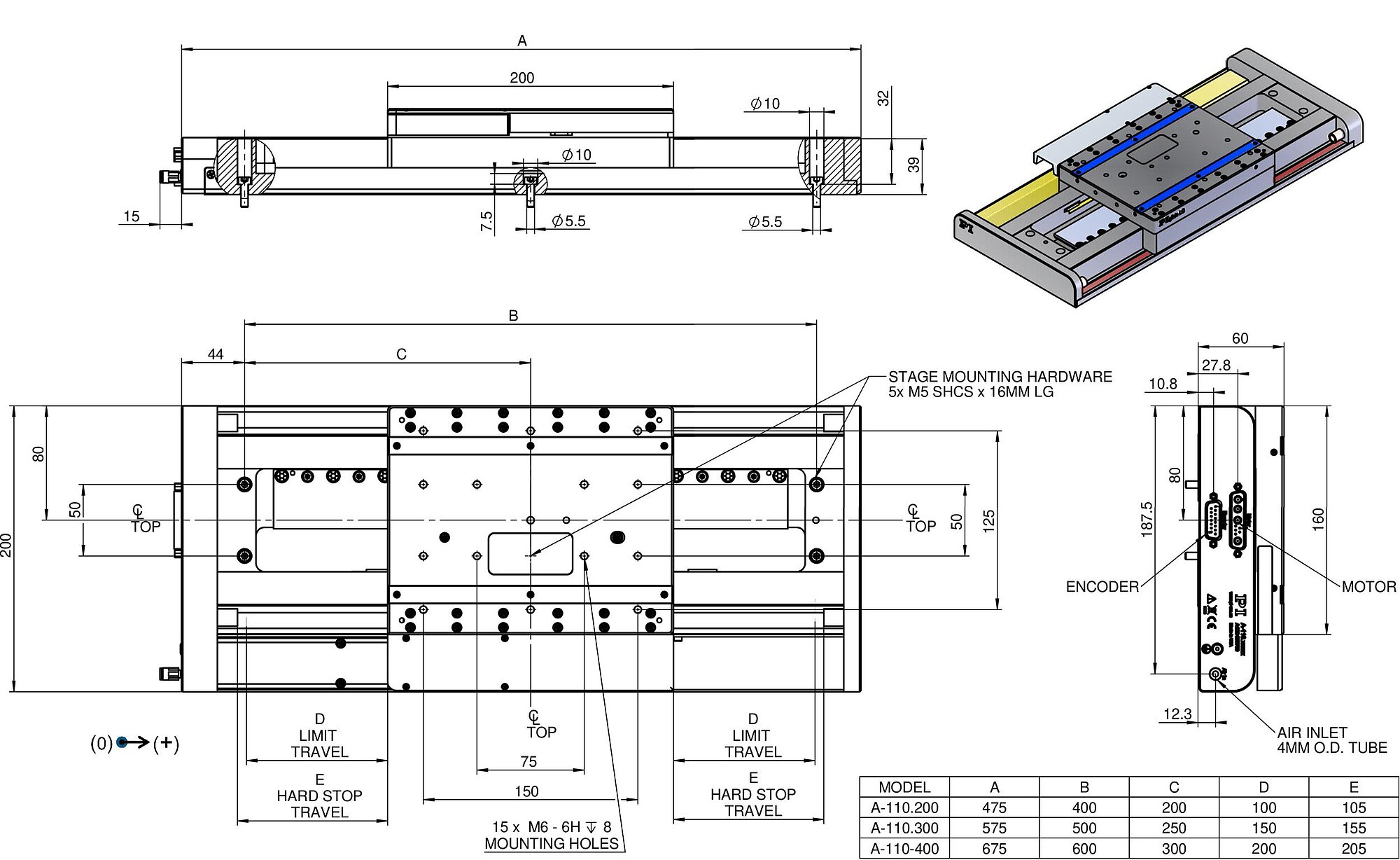
| Travel range in X | 50 mm | 50 mm | 100 mm | 100 mm | 200 mm | 200 mm | 300 mm | 300 mm | 400 mm | 400 mm | |
| Acceleration in X, unloaded | 20 m/s² | 20 m/s² | 20 m/s² | 20 m/s² | 20 m/s² | 20 m/s² | 20 m/s² | 20 m/s² | 20 m/s² | 20 m/s² | max. |
| Maximum velocity in X, unloaded | 500 mm/s | 500 mm/s | 500 mm/s | 500 mm/s | 1000 mm/s | 1000 mm/s | 1000 mm/s | 1000 mm/s | 1000 mm/s | 1000 mm/s | |
| Straightness (Linear crosstalk in Y with motion in X) | ± 0.5 µm | ± 0.5 µm | ± 0.5 µm | ± 0.5 µm | ± 0.75 µm | ± 0.75 µm | ± 1 µm | ± 1 µm | ± 1 µm | ± 1 µm | max. |
| Flatness (Linear crosstalk in Z with motion in X) | ± 0.5 µm | ± 0.5 µm | ± 0.5 µm | ± 0.5 µm | ± 0.75 µm | ± 0.75 µm | ± 1 µm | ± 1 µm | ± 1 µm | ± 1 µm | max. |
| Pitch (Rotational crosstalk in θY with motion in X) | ± 7.5 µrad | ± 7.5 µrad | ± 10 µrad | ± 10 µrad | ± 10 µrad | ± 10 µrad | ± 17.5 µrad | ± 17.5 µrad | ± 20 µrad | ± 20 µrad | max. |
| Yaw (Rotational crosstalk in θZ with motion in X) | ± 7.5 µrad | ± 7.5 µrad | ± 10 µrad | ± 10 µrad | ± 10 µrad | ± 10 µrad | ± 17.5 µrad | ± 17.5 µrad | ± 20 µrad | ± 20 µrad | max. |
| Positioning | A-110.050A1 | A-110.050B1 | A-110.100A1 | A-110.100B1 | A-110.200A1 | A-110.200B1 | A-110.300A1 | A-110.300B1 | A-110.400A1 | A-110.400B1 | Tolerance |
| Bidirectional repeatability in X | ± 0.1 µm | ± 0.1 µm | ± 0.1 µm | ± 0.1 µm | ± 0.1 µm | ± 0.1 µm | ± 0.1 µm | ± 0.1 µm | ± 0.1 µm | ± 0.1 µm | typ. |
| Positioning accuracy in X, calibrated | ± 0.5 µm | ± 0.5 µm | ± 0.5 µm | ± 0.5 µm | ± 0.5 µm | ± 0.5 µm | ± 0.5 µm | ± 0.5 µm | ± 0.5 µm | ± 0.5 µm | typ. |
| Positioning accuracy in X, uncalibrated | ± 1.5 µm | ± 1.5 µm | ± 1.5 µm | ± 1.5 µm | ± 2 µm | ± 1.5 µm | ± 3 µm | ± 1.5 µm | ± 4 µm | ± 1.5 µm | typ. |
| Integrated sensor | Incremental linear encoder | Absolute linear encoder | Incremental linear encoder | Absolute linear encoder | Incremental linear encoder | Absolute linear encoder | Incremental linear encoder | Absolute linear encoder | Incremental linear encoder | Absolute linear encoder | |
| Sensor signal | Sin/cos, 1 V peak-peak | BiSS-C | Sin/cos, 1 V peak-peak | BiSS-C | Sin/cos, 1 V peak-peak | BiSS-C | Sin/cos, 1 V peak-peak | BiSS-C | Sin/cos, 1 V peak-peak | BiSS-C | |
| Sensor resolution | 4.88 nm | 1 nm | 4.88 nm | 1 nm | 4.88 nm | 1 nm | 4.88 nm | 1 nm | 4.88 nm | 1 nm | |
| Sensor signal period | 20 µm | 20 µm | 20 µm | 20 µm | 20 µm | ||||||
| Reference switch | Encoder index | Encoder index | Encoder index | Encoder index | Encoder index | ||||||
| Limit switches | Hall effect | Hall effect | Hall effect | Hall effect | Hall effect | ||||||
| Drive Properties | A-110.050A1 | A-110.050B1 | A-110.100A1 | A-110.100B1 | A-110.200A1 | A-110.200B1 | A-110.300A1 | A-110.300B1 | A-110.400A1 | A-110.400B1 | Tolerance |
| Drive type | Ironless 3-phase linear motor | Ironless 3-phase linear motor | Ironless 3-phase linear motor | Ironless 3-phase linear motor | Ironless 3-phase linear motor | Ironless 3-phase linear motor | Ironless 3-phase linear motor | Ironless 3-phase linear motor | Ironless 3-phase linear motor | Ironless 3-phase linear motor | |
| Nominal voltage | 48 V | 48 V | 48 V | 48 V | 48 V | 48 V | 48 V | 48 V | 48 V | 48 V | |
| Peak voltage | 60 V | 60 V | 60 V | 60 V | 60 V | 60 V | 60 V | 60 V | 60 V | 60 V | |
| Nominal current, RMS | 1.6 A | 1.6 A | 1.6 A | 1.6 A | 3.2 A | 3.2 A | 3.2 A | 3.2 A | 3.2 A | 3.2 A | typ. |
| Peak current, RMS | 4.2 A | 4.2 A | 4.2 A | 4.2 A | 6.9 A | 6.9 A | 6.9 A | 6.9 A | 6.9 A | 6.9 A | typ. |
| Drive force in negative direction of motion in X | 20 N | 20 N | 20 N | 20 N | 39 N | 39 N | 39 N | 39 N | 39 N | 39 N | typ. |
| Drive force in positive direction of motion in X | 20 N | 20 N | 20 N | 20 N | 39 N | 39 N | 39 N | 39 N | 39 N | 39 N | typ. |
| Peak force in negative direction of motion in X | 60 N | 60 N | 60 N | 60 N | 85 N | 85 N | 85 N | 85 N | 85 N | 85 N | |
| Peak force in positive direction of motion in X | 60 N | 60 N | 60 N | 60 N | 85 N | 85 N | 85 N | 85 N | 85 N | 85 N | |
| Force constant | 4.1 N/A | 4.1 N/A | 4.1 N/A | 4.1 N/A | 12.3 N/A | 12.3 N/A | 12.3 N/A | 12.3 N/A | 12.3 N/A | 12.3 N/A | |
| Resistance phase-phase | 11 Ω | 11 Ω | 11 Ω | 11 Ω | 3.6 Ω | 3.6 Ω | 3.6 Ω | 3.6 Ω | 3.6 Ω | 3.6 Ω | typ. |
| Inductance phase-phase | 6 mH | 6 mH | 6 mH | 6 mH | 1.24 mH | 1.24 mH | 1.24 mH | 1.24 mH | 1.24 mH | 1.24 mH | |
| Back EMF phase-phase | 10 V·s/m | 10 V·s/m | 10 V·s/m | 10 V·s/m | 10.1 V·s/m | 10.1 V·s/m | 10.1 V·s/m | 10.1 V·s/m | 10.1 V·s/m | 10.1 V·s/m | max. |
| Pole pitch N-N | 33.6 mm | 33.6 mm | 33.6 mm | 33.6 mm | 24 mm | 24 mm | 24 mm | 24 mm | 24 mm | 24 mm | |
| Mechanical Properties | A-110.050A1 | A-110.050B1 | A-110.100A1 | A-110.100B1 | A-110.200A1 | A-110.200B1 | A-110.300A1 | A-110.300B1 | A-110.400A1 | A-110.400B1 | Tolerance |
| Guide | Air bearing guide with preload | Air bearing guide with preload | Air bearing guide with preload | Air bearing guide with preload | Air bearing guide with preload | Air bearing guide with preload | Air bearing guide with preload | Air bearing guide with preload | Air bearing guide with preload | Air bearing guide with preload | |
| Moved mass in X, unloaded | 2500 g | 2500 g | 2500 g | 2500 g | 2600 g | 2600 g | 2600 g | 2600 g | 2600 g | 2600 g | |
| Permissible push force in Z | 100 N | 100 N | 100 N | 100 N | 100 N | 100 N | 100 N | 100 N | 100 N | 100 N | max. |
| Overall mass | 6300 g | 6300 g | 7500 g | 7500 g | 11000 g | 11000 g | 12000 g | 12000 g | 14000 g | 14000 g | |
| Material | Hardcoat aluminum, stainless steel mounting hardware | Hardcoat aluminum, stainless steel mounting hardware | Hardcoat aluminum, stainless steel mounting hardware | Hardcoat aluminum, stainless steel mounting hardware | Hardcoat aluminum, stainless steel mounting hardware | Hardcoat aluminum, stainless steel mounting hardware | Hardcoat aluminum, stainless steel mounting hardware | Hardcoat aluminum, stainless steel mounting hardware | Hardcoat aluminum, stainless steel mounting hardware | Hardcoat aluminum, stainless steel mounting hardware | |
| Miscellaneous | A-110.050A1 | A-110.050B1 | A-110.100A1 | A-110.100B1 | A-110.200A1 | A-110.200B1 | A-110.300A1 | A-110.300B1 | A-110.400A1 | A-110.400B1 | Tolerance |
| Connector | D-sub 9W4 (m) | D-sub 9W4 (m) | D-sub 9W4 (m) | D-sub 9W4 (m) | D-sub 9W4 (m) | D-sub 9W4 (m) | D-sub 9W4 (m) | D-sub 9W4 (m) | D-sub 9W4 (m) | D-sub 9W4 (m) | |
| Sensor connector | D-sub 15-pole (m) | D-sub 15-pole (m) | D-sub 15-pole (m) | D-sub 15-pole (m) | D-sub 15-pole (m) | D-sub 15-pole (m) | D-sub 15-pole (m) | D-sub 15-pole (m) | D-sub 15-pole (m) | D-sub 15-pole (m) | |
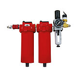
| Operating pressure | 515 to 585 kPa | 515 to 585 kPa | 515 to 585 kPa | 515 to 585 kPa | 515 to 585 kPa | 515 to 585 kPa | 515 to 585 kPa | 515 to 585 kPa | 515 to 585 kPa | 515 to 585 kPa | |
| Air consumption | 28 L/min | 28 L/min | 28 L/min | 28 L/min | 28 L/min | 28 L/min | 28 L/min | 28 L/min | 28 L/min | 28 L/min | max. |
| Air quality | Clean (filtered up to 1.0 µm or better) - ISO 8573–1 class 1 Oil free - ISO 8573–1 class 1 Dry (-15 °C dew point) - ISO 8573–1 class 3 | Clean (filtered up to 1.0 µm or better) - ISO 8573–1 class 1 Oil free - ISO 8573–1 class 1 Dry (-15 °C dew point) - ISO 8573–1 class 3 | Clean (filtered up to 1.0 µm or better) - ISO 8573–1 class 1 Oil free - ISO 8573–1 class 1 Dry (-15 °C dew point) - ISO 8573–1 class 3 | Clean (filtered up to 1.0 µm or better) - ISO 8573–1 class 1 Oil free - ISO 8573–1 class 1 Dry (-15 °C dew point) - ISO 8573–1 class 3 | Clean (filtered up to 1.0 µm or better) - ISO 8573–1 class 1 Oil free - ISO 8573–1 class 1 Dry (-15 °C dew point) - ISO 8573–1 class 3 | Clean (filtered up to 1.0 µm or better) - ISO 8573–1 class 1 Oil free - ISO 8573–1 class 1 Dry (-15 °C dew point) - ISO 8573–1 class 3 | Clean (filtered up to 1.0 µm or better) - ISO 8573–1 class 1 Oil free - ISO 8573–1 class 1 Dry (-15 °C dew point) - ISO 8573–1 class 3 | Clean (filtered up to 1.0 µm or better) - ISO 8573–1 class 1 Oil free - ISO 8573–1 class 1 Dry (-15 °C dew point) - ISO 8573–1 class 3 | Clean (filtered up to 1.0 µm or better) - ISO 8573–1 class 1 Oil free - ISO 8573–1 class 1 Dry (-15 °C dew point) - ISO 8573–1 class 3 | Clean (filtered up to 1.0 µm or better) - ISO 8573–1 class 1 Oil free - ISO 8573–1 class 1 Dry (-15 °C dew point) - ISO 8573–1 class 3 | |
| Recommended controllers / drivers | A-81x, A-82x | A-81x, A-82x | A-81x, A-82x | A-81x, A-82x | A-81x, A-82x | A-81x, A-82x | A-81x, A-82x | A-81x, A-82x | A-81x, A-82x | A-81x, A-82x | |
| Operating temperature range | 15 to 25 °C | 15 to 25 °C | 15 to 25 °C | 15 to 25 °C | 15 to 25 °C | 15 to 25 °C | 15 to 25 °C | 15 to 25 °C | 15 to 25 °C | 15 to 25 °C |
A-110 PIglide LC Linear Air Bearing Stages
All Positioning Stages are not Created Equal. Author: Matt Reck, PI
Ask for a free quote on quantities required, prices, and lead times or describe your desired modification.
PIglide LC linear stage, air bearings, 50 mm travel range, incremental linear encoder with sin/cos signal transmission, 20 µm sensor signal period, ironless 3-phase linear motor, 48 V
PIglide LC linear stage, air bearings, 50 mm travel range, absolute linear encoder with BiSS-C signal transmission, 1 nm sensor resolution, ironless 3-phase linear motor, 48 V
PIglide LC linear stage, air bearings, 100 mm travel range, incremental linear encoder with sin/cos signal transmission, 20 µm sensor signal period, ironless 3-phase linear motor, 48 V
PIglide LC linear stage, air bearings, 100 mm travel range, absolute linear encoder with BiSS-C signal transmission, 1 nm sensor resolution, ironless 3-phase linear motor, 48 V
PIglide LC linear stage, air bearings, 200 mm travel range, incremental linear encoder with sin/cos signal transmission, 20 µm sensor signal period, ironless 3-phase linear motor, 48 V
PIglide LC linear stage, air bearings, 200 mm travel range, absolute linear encoder with BiSS-C signal transmission, 1 nm sensor resolution, ironless 3-phase linear motor, 48 V
PIglide LC linear stage, air bearings, 300 mm travel range, incremental linear encoder with sin/cos signal transmission, 20 µm sensor signal period, ironless 3-phase linear motor, 48 V
PIglide LC linear stage, air bearings, 300 mm travel range, absolute linear encoder with BiSS-C signal transmission, 1 nm sensor resolution, ironless 3-phase linear motor, 48 V
PIglide LC linear stage, air bearings, 400 mm travel range, incremental linear encoder with sin/cos signal transmission, 20 µm sensor signal period, ironless 3-phase linear motor, 48 V
PIglide LC linear stage, air bearings, 400 mm travel range, absolute linear encoder with BiSS-C signal transmission, 1 nm sensor resolution, ironless 3-phase linear motor, 48 V
Quickly receive an answer to your question by email or phone from a local PI sales engineer.