MPL-W10 Modular Configurable Precision Linear Stage
Versatile – Spindle-Driven – Compact Design
- 50 mm to 300 mm travel range
- Servo or stepper motor
- Linear or rotary encoder
- 1 mm, 2 mm, or 5 mm spindle pitch
- Motor brake option
- Limit switch options
- Customer interface options
- Drag chain options
- And a lot of further options

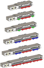
Motor orientation: straight
Connector orientation: 0°
Connector orientation: 180°
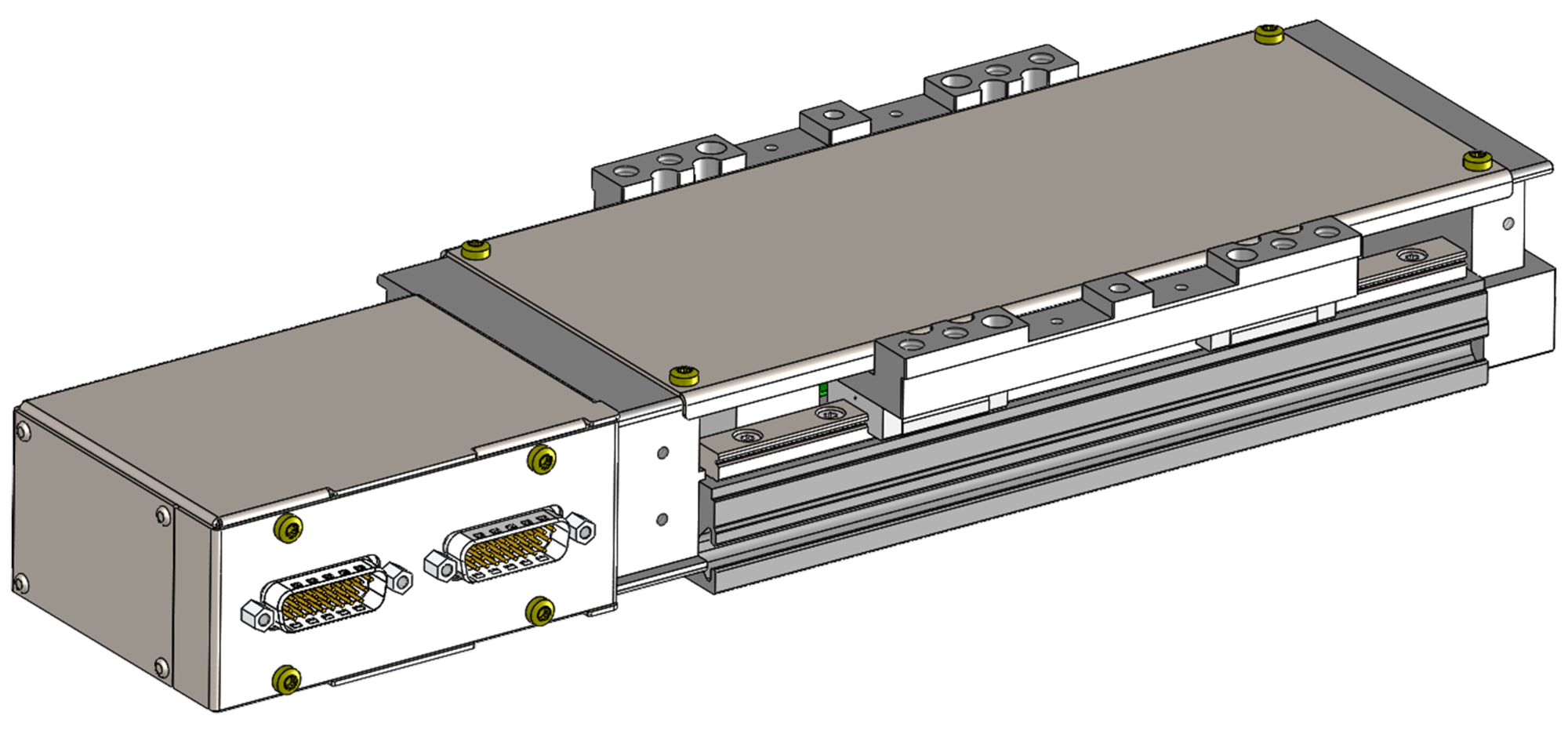
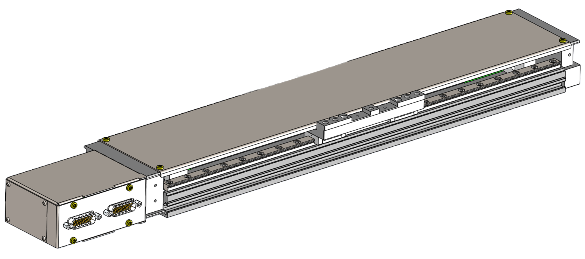
MPL-W10 without customer interface
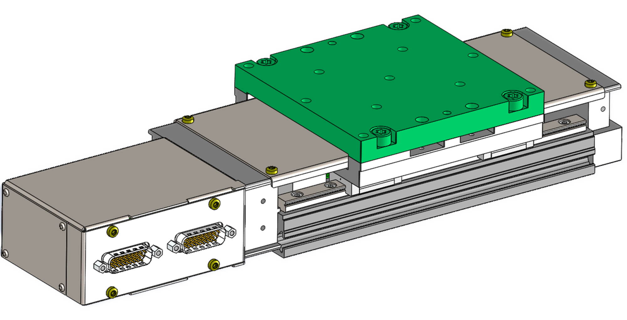
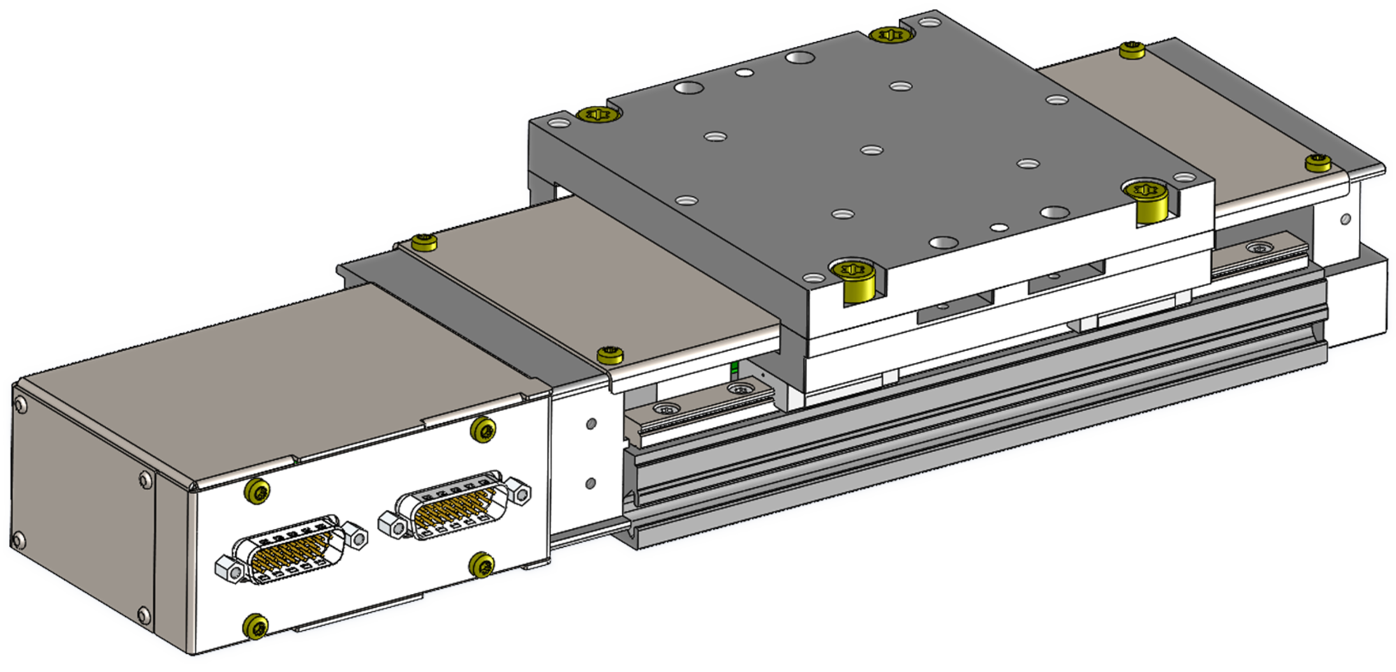
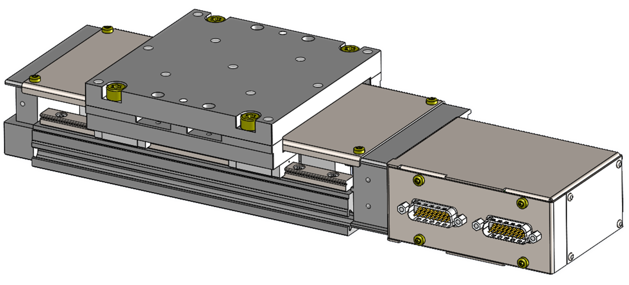
MPL-W10 with standard customer interface
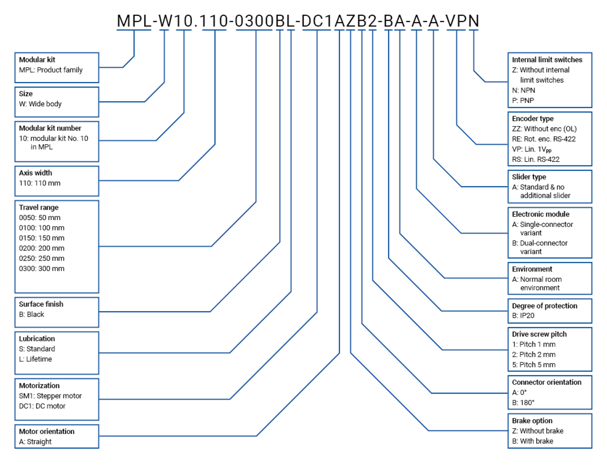
MPL-W10 product key
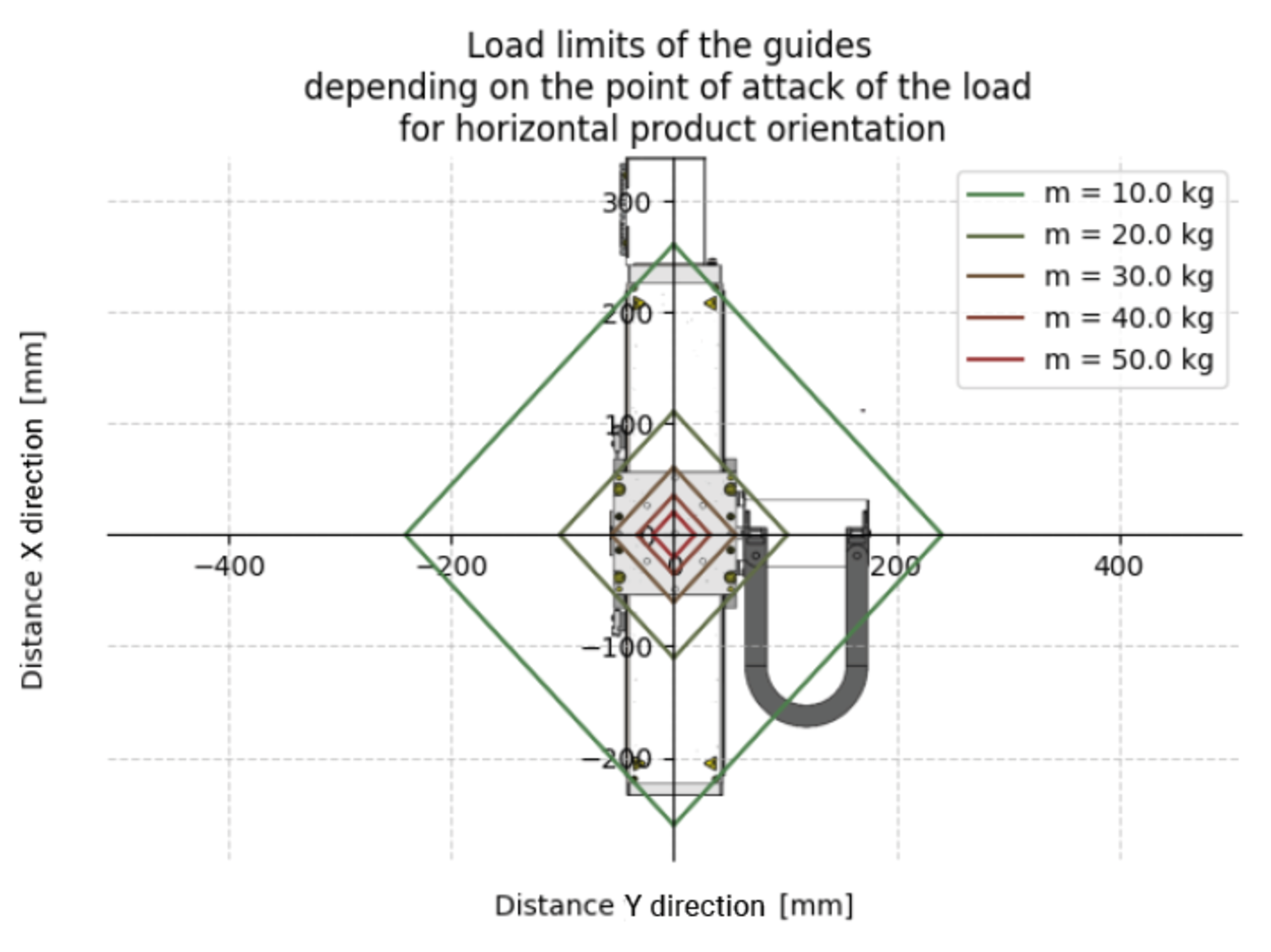
Load limits of the guides
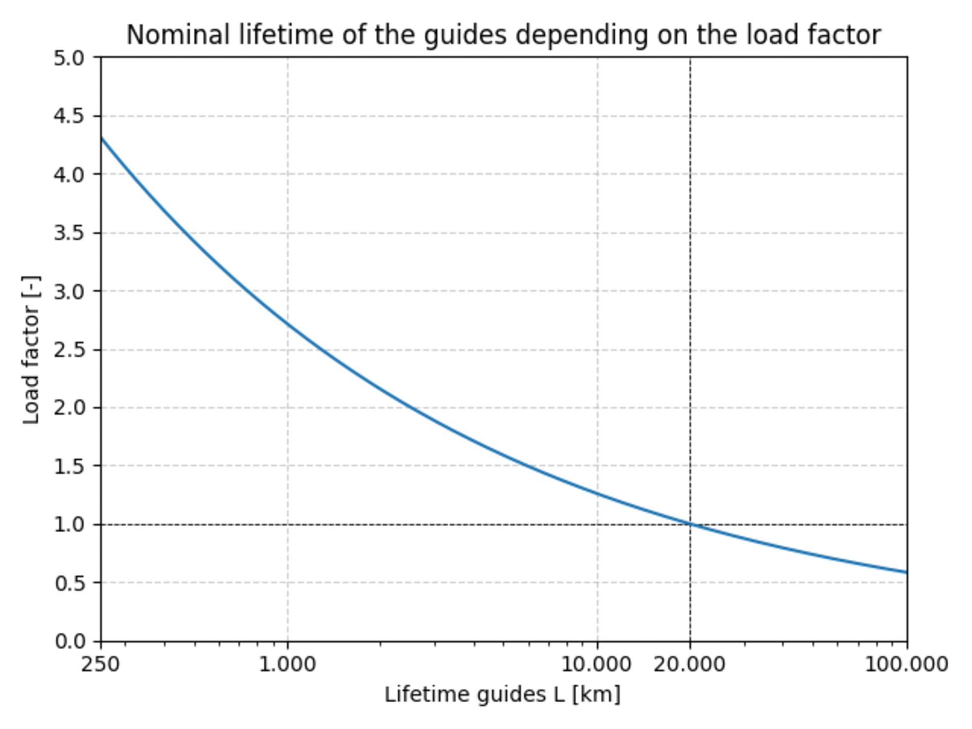
Lifetime of guides
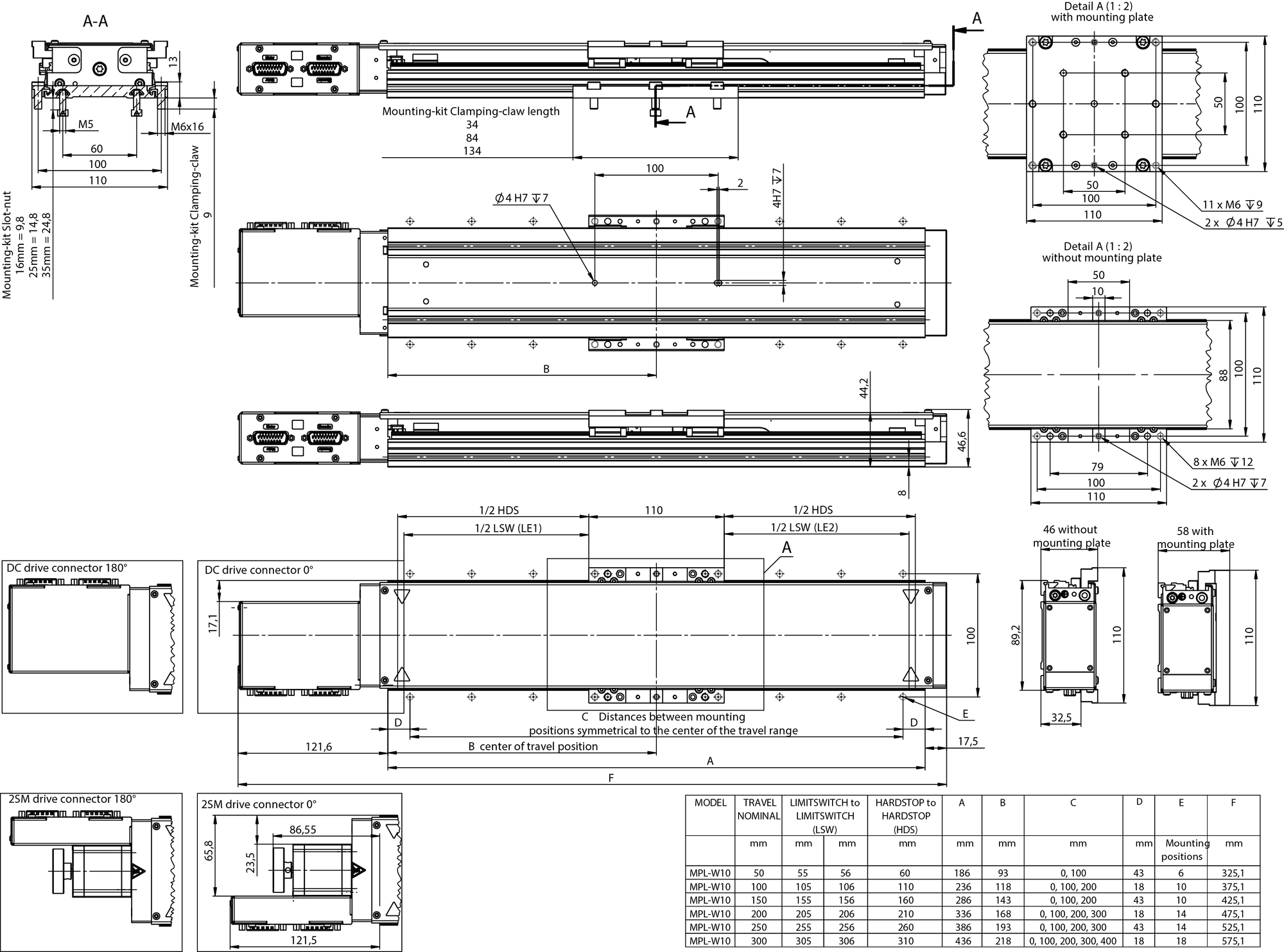
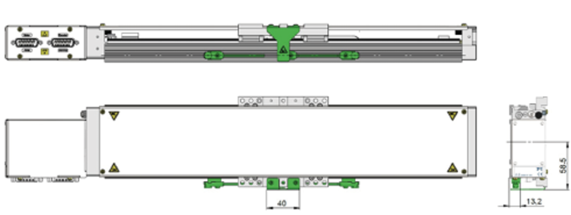
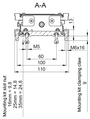
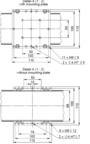
MPL-W10 , dimensions in mm. Note that a comma may be used in the drawings instead of a decimal point.
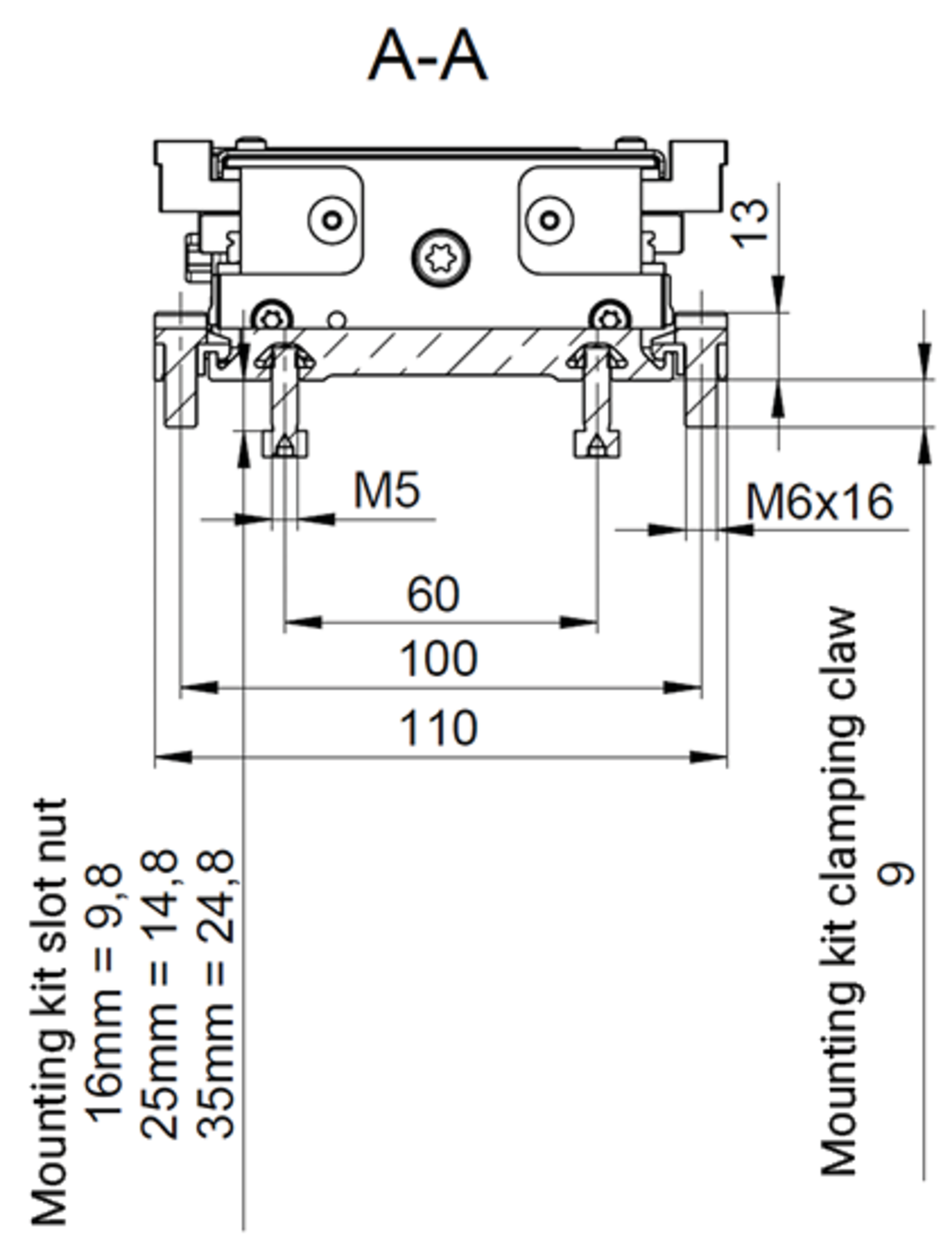
Details: mounting with slot nuts, mounting with clamping claws
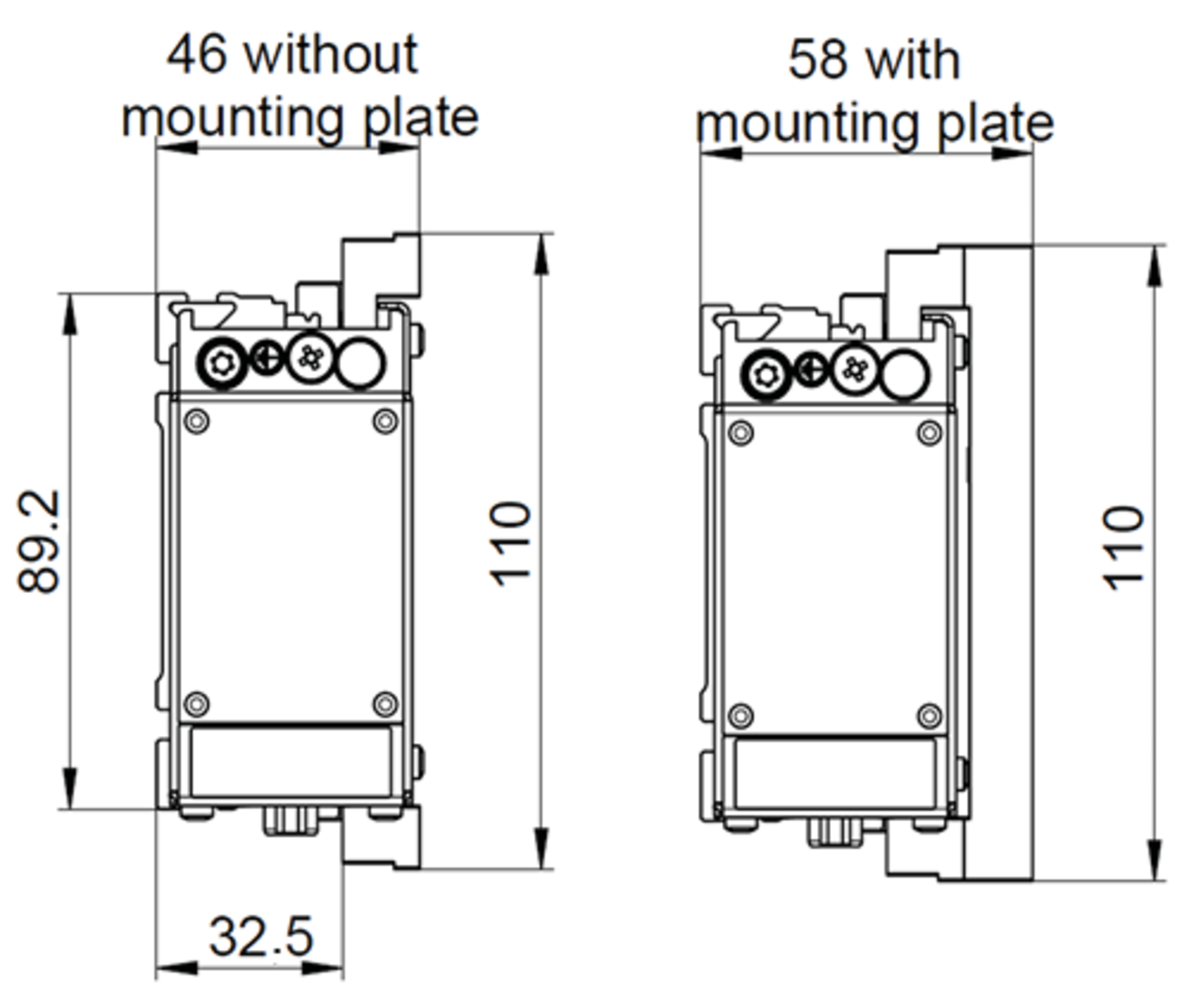
MPL-W10 with and without customer interface (mounting plate): side view
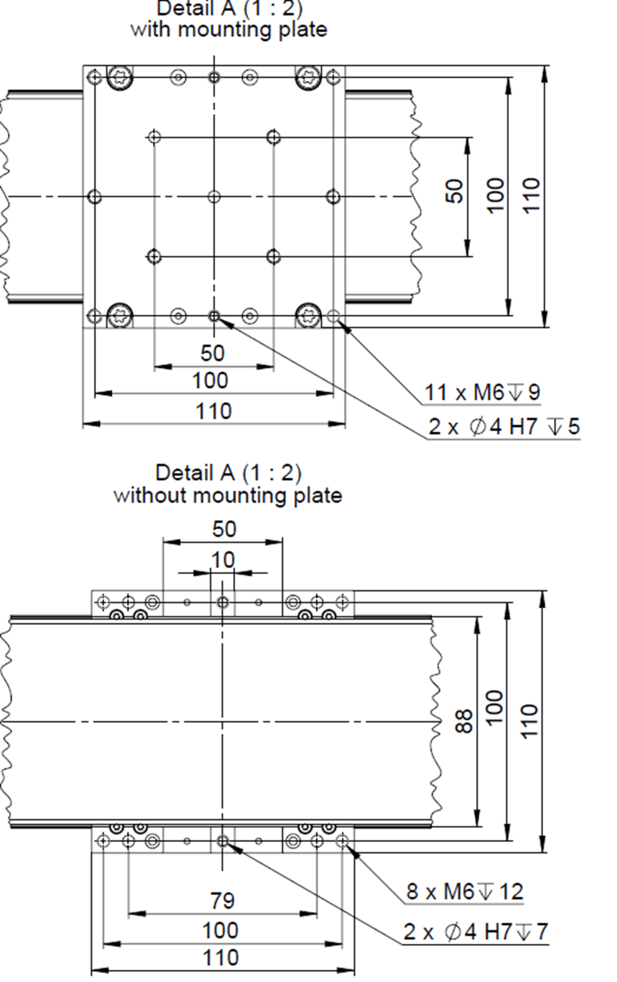
MPL-W10 with and without customer interface (mounting plate): view from above
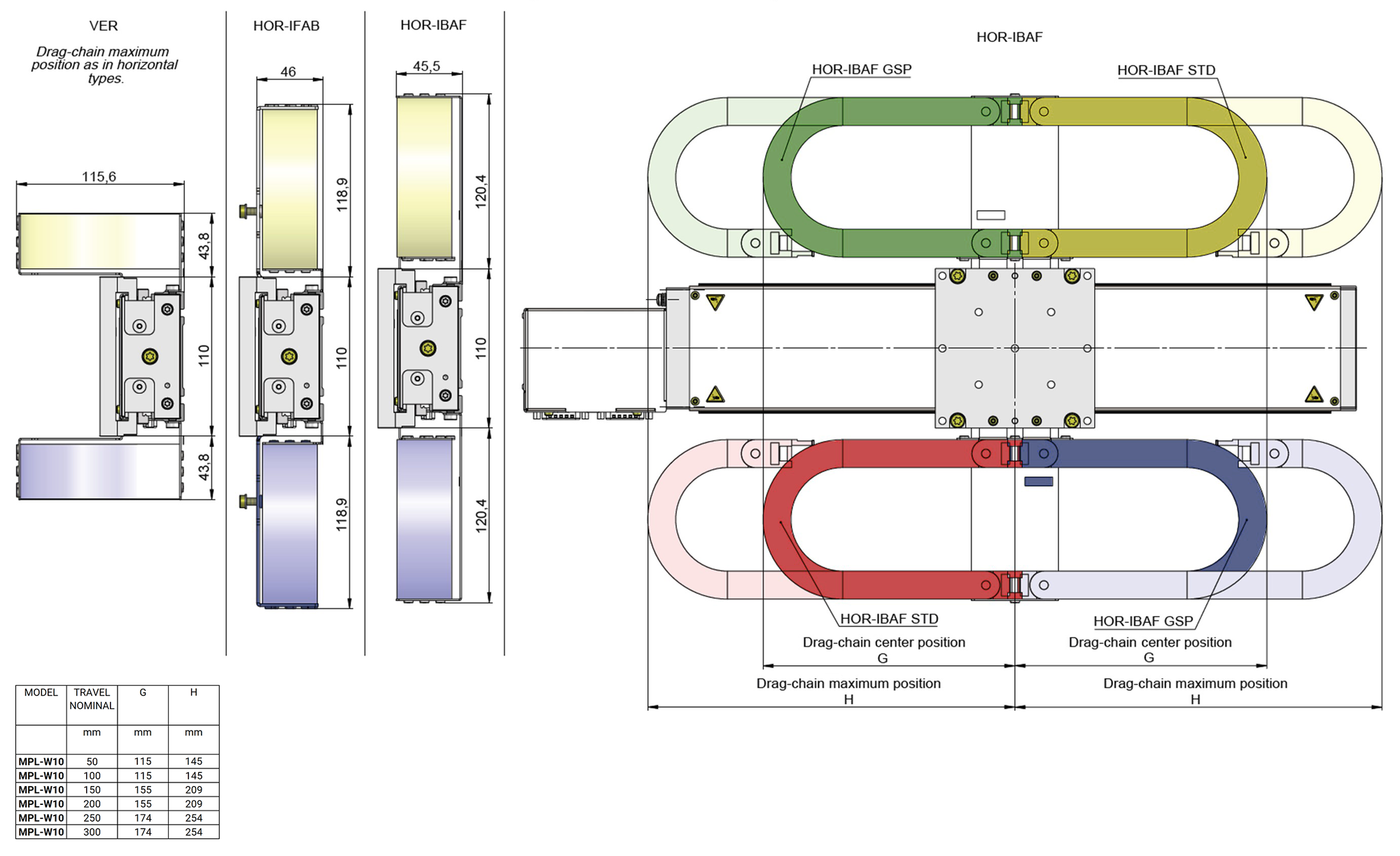
Drag chain: Mounting options
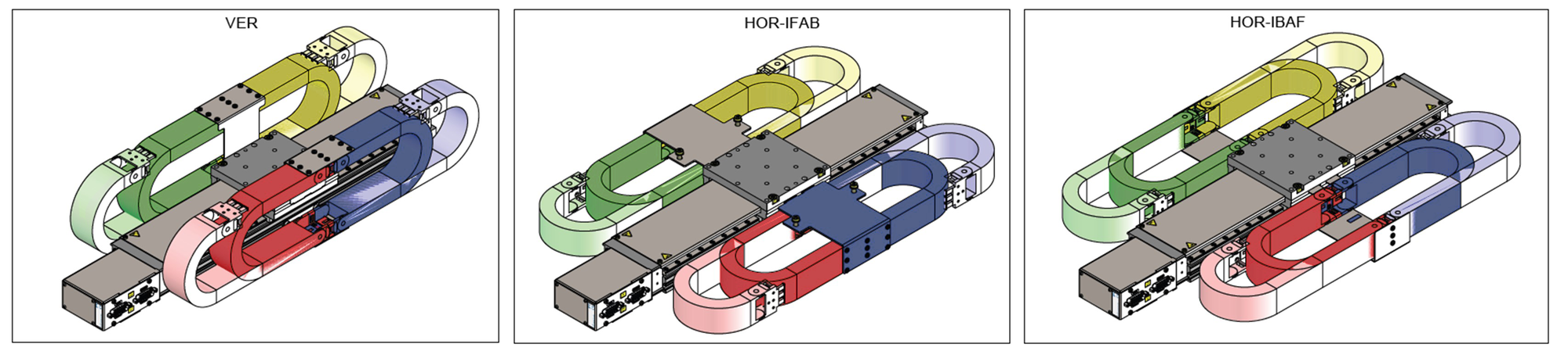
Drag chain: Mounting options 3D
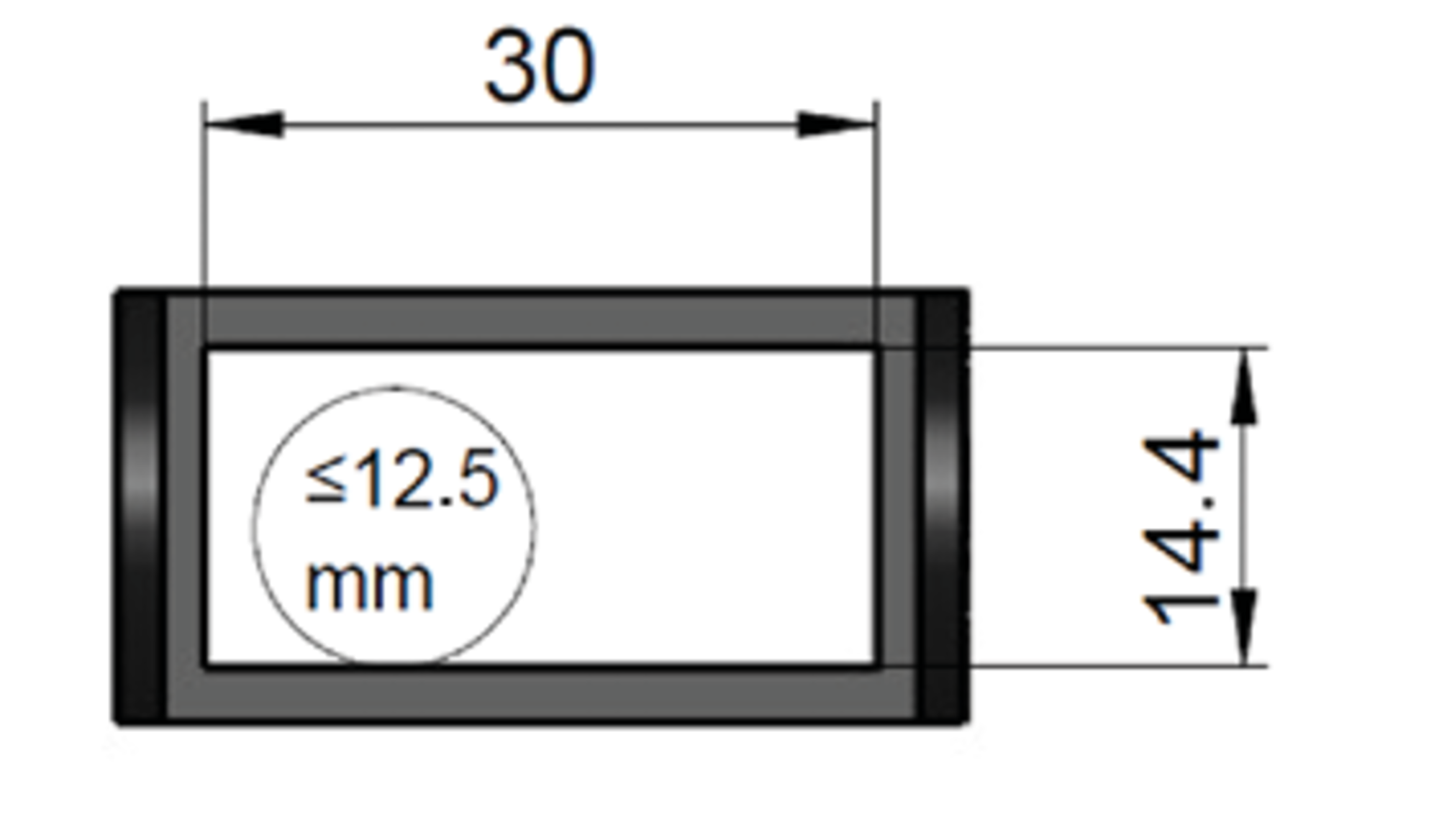
Drag chain: interior cross section. Maximum recommended cable diameter 12.5 mm. Cable bending radius 45 mm in drag chain.
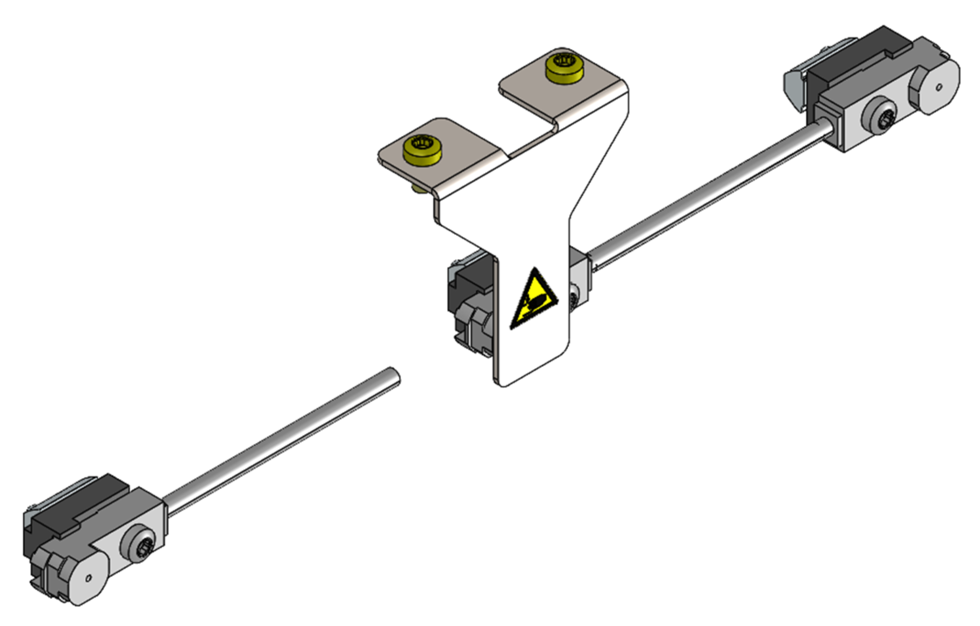
External sensor: option with limit switches and reference switch
External sensor (shown in green), dimensions in mm

Overview of clamping claw mounting kits
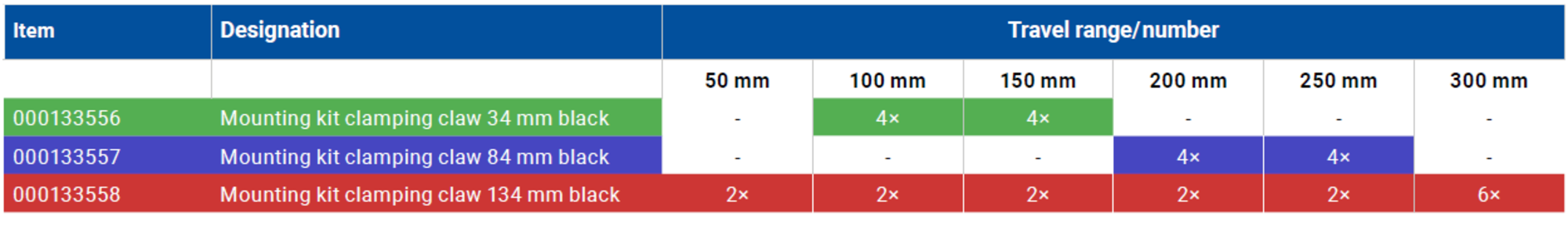
Clamping claws for various travel ranges
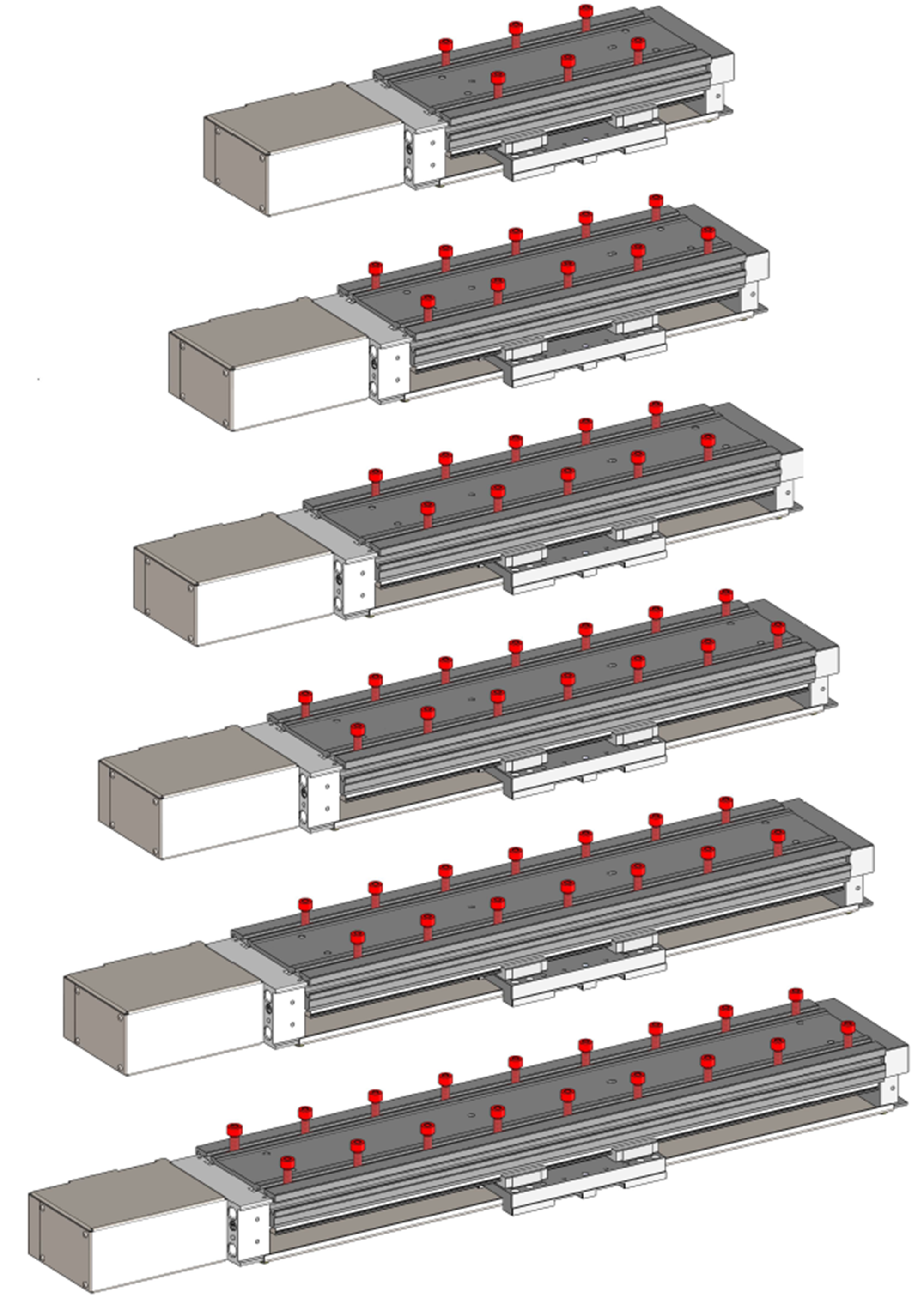
Overview of slot nut mounting kits
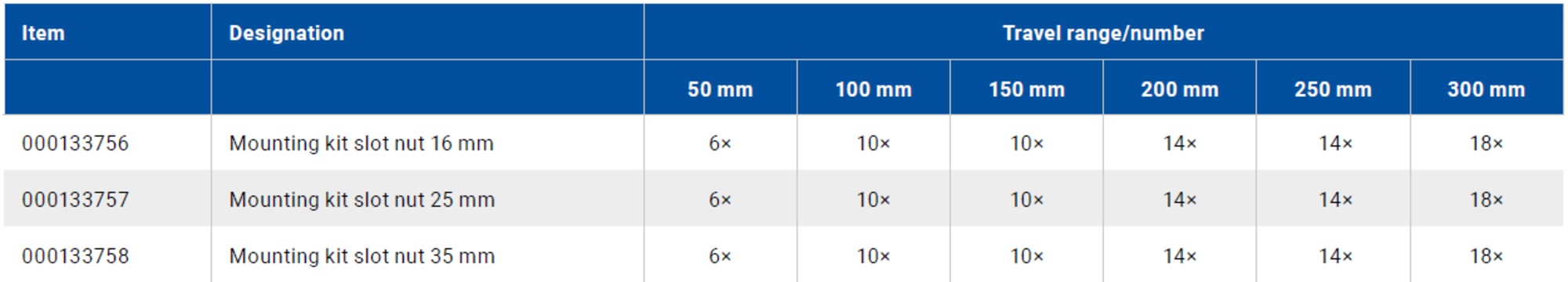
Slot nuts for various travel ranges


Highlights
Discover the future of precise handling with PI’s configurable MPL linear stage. Specifically designed for precision and reliability, our spindle drive technology offers unique advantages that will push your application to a new level.
Tailored solution: Optimize your processes by configuring the most suitable linear stage for your application. This customized approach enhances productivity by meeting your precise operational needs, thereby contributing to consistent quality and efficiency.
Exceptional accuracy: Our linear stage is engineered for high-class precision, guaranteeing accuracy for critical tasks in positioning applications, e.g., XY raster scan for wafer inspection. Every part meets the highest of standards, reducing error and improving overall product quality.
Consistently high quality: PI’s manufacturing processes ensure that every product maintains a uniformly high level of precision and quality. This uniformity is crucial for maintaining consistent performance and reliability in your application, significantly reducing variations and ensuring each product meets rigorous standards.
Future-proof custom solutions: The individual adaptability of our modular kit keeps you flexible and efficient, no matter how your requirements evolve. Invest in tomorrow’s technology today.
Rely on precision, reliability, and flexible configurability — choose the MPL linear stages with spindle drive for the most demanding applications. The spindle-driven MPL linear axis is the perfect solution for applications where maximum precision and stability are required. It enables exact vertical adjustment of the camera or lens, ensuring optimal focus capabilities in optical inspection systems and similar applications.
Thanks to the mechanical self-locking feature of the spindle/stepper motor combination, the axis remains securely in position even without a power supply. This means there is no uncontrolled lowering in the event of a power failure, no additional holding current, and no need for brakes.
Take the next step towards technological advancement and secure your leading position in the market. Contact us (info@pi.de) for personalized consultation and a custom solution precisely tailored to your needs.
The individual MPL modules are described in detail below.
Travel range
The travel range describes the greatest possible movement in the direction of motion. The following options are available:
50 mm
100 mm
150 mm
200 mm
250 mm
300 mm
Motor
DC motor
Preferred for dynamic applications
Preferred where smooth performance is required
Stepper motor
Precise positioning and repeatability
Excellent torque at low speed, preferred when strong starting torque is required
20 mNm holding torque to maintain a position without power
Motor brake
The addition of a motor brake is available for the DC motor, which makes it possible to hold a position, even in the de-energized state.
Especially recommended if the stage is used as a Z axis (motion in the direction of gravity) to prevent unintentional changes in position in the event of a power failure.
Motor orientation
Straight
Narrower, thus recommended when the installation space is limited in width
More cost-effective
Connector orientation
Change the orientation of the motor module and thus the orientation of the connectors to route the cables optimally:
0°
180°
Spindle pitch
The spindle pitch describes the distance traveled by the spindle nut per revolution of the spindle in millimeters.
The spindle pitches 1 mm, 2 mm, and 5 mm are available.
Larger spindle pitches increase velocity
Smaller spindle pitches increase drive force
Smaller spindle pitches increase positioning accuracy
Encoder
An encoder enables the position of the slider to be operated in a closed control loop, thereby allowing more precise position control.
No encoder
Open-loop control for stepper motor only
No extra charge for the encoder
Linear 1 Vpp
Highest resolution, for the most accurate applications
Accounts for all elasticities in the powertrain
Linear RS-422
More robust than linear 1 Vpp
Accounts for all elasticities in the powertrain
Rotational RS-422
Most robust encoder
Most cost-effective encoder
At the motor shaft
Limit switches
To prevent mechanical passage and thus damage to the stage, the use of limit switches is recommended.
External limit switches
External limit switches are easier to adapt to the limits of the application
More secure than software limits for protecting application setup
Internal limit switches
Easy setup with secure stop at travel end
Internal limit switches provide greater security because they cannot be moved
Choose your logic between NPN and PNP (5 V - 24 V)
Customer interface
No customer interface
Less height in an XY setup
Setup can be directly mounted on the slider interface
Standard customer interface
Providing most common hole patterns,
e.g., 50 mm × 50 mm and 100 mm × 100 mm
Drag chain (optional)
The drag chain can be selected as an option.
To ensure the safe operation of an XY system consisting of two MPL stages, a drag chain for the top stage is recommended, especially for dynamic applications.
The drag chain can be attached to the stage in eight different positions. These include four vertical and four horizontal positions. Within the horizontal positions, the following additional variants are available: HOR-IFAB whereby the inner part of the drag chain is fixed and outer part moves, and HOR-IBAF whereby the inner part moves and the outer part is fixed. The drag chain is an accessory and can be attached by the customer. The drag chain can either be attached to the side slots or to the clamping claws.
If necessary, two drag chains can also be attached on opposite sides.
Lubrication
Lifetime lubrication
No relubrication necessary
Best choice for moderate load/dynamics
Standard lubrication
For high loads as well as dynamic or continuous operation
Depending on application, relubrication must be performed every 4 to 6 months or after a maximum distance of 300 km
Surface finish
Black anodized aluminum parts:
Corrosion protection
Anodic coating makes the material less sensitive to abrasion and scratches
Visually appealing
Degree of protection
IP2x:
Cost-effective
Product offers sufficient protection against the ingress of solid objects larger than 12.5 mm in diameter (e.g., fingers)
Mounting kit
Kit 1: Clamping claw
The clamping claw mounting kit can be used for all configuration variants of the stage. It serves to mount the axis in the application environment. The clamping claws are inserted into the lateral slot and attached to the surface with screws. The screws are included with the clamping claws in various lengths.
Kit 2: Slot nut
The slot nut mounting kit can be used for all configuration variants of the stage. It serves to mount the axis in the application environment. The slot nuts are inserted into the slot located on the bottom of the stage and screwed to the surface through a through-hole. The kits include various screw lengths.
Specifications
Specifications
| Drive Type | DC Motor | Stepper Motor | |||||||
| Spindle Pitch [mm] | 1 | 2 | 5 | 1 | 2 | 5 | |||
| Maximum velocity in X, v unloaded [mm/s] | 50 | 100 | 250 | 20 | 40 | 100 | |||
| Acceleration a [m/s2] | 0.9 | 1.7 | 3.5 | 0.7 | 1.4 | 3.2 | |||
| Minimum incremental motion in X (max.) [μm] | Encoder | 1 Vpp | 0.05 | 0.1 | 0.2 | 0.05 | 0.1 | 0.2 | |
| RS-422 | 0.5 | 0.5 | 0.5 | 0.5 | 0.5 | 0.5 | |||
| Rot. | 2 | 5 | 10 | – | – | – | |||
| None | – | – | – | 2 | 5 | 10 | |||
| Unidirectional repeatability in X (max.) [μm] | Encoder | 1 Vpp | ±0.5 | ±0.5 | ±1 | ±0.5 | ±0.5 | ±1 | |
| RS-422 | ±0.5 | ±0.5 | ±1 | ±0.5 | ±0.5 | ±1 | |||
| Rot. | ±2 | ±2 | ±5 | – | – | – | |||
| None | – | – | – | ±5 | ±5 | ±10 | |||
| Bidirectional repeatability in X (max.) [μm] | Encoder | 1 Vpp | 1 | 1 | 2 | 1 | 1 | 2 | |
| RS-422 | 1 | 1 | 2 | 1 | 1 | 2 | |||
| Rot. | 5 | 5 | 10 | – | – | – | |||
| None | – | – | – | 10 | 10 | 20 | |||
| Drive Type | DC Motor | Stepper Motor | |||||||
| Spindle pitch [mm] | 1 | 2 | 5 | 1 | 2 | 5 | |||
| Drive force in direction of motion in X [N] | 100 | 50 | 20 | 100 | 100 | 40 | |||
| Holding force in X, passive [N] | – | – | – | 50 | 40 | 20 | |||
| Permissible force in Z [N] | 100* | 100* | 100* | 100* | 100* | 100* | |||
| Permissible force in Y [N] | 100 | 100 | 100 | 100 | 100 | 100 | |||
| Permissible force in X [N] | 100 | 50 | 20 | 100 | 100 | 40 | |||
| Permissible torque in θX [Nm] | 30 | 30 | 30 | 30 | 30 | 30 | |||
| Permissible torque in θY [Nm] | 20 | 20 | 20 | 20 | 20 | 20 | |||
| Permissible torque in θZ [Nm] | 20 | 20 | 20 | 20 | 20 | 20 | |||
| Holding brake | Optional for DC motor — holding force 50 N | ||||||||
| Drive screw type | Ball screw | ||||||||
| Guide | Recirculating linear ball bearing | ||||||||
| Moved mass [g] | Depends on configuration | ||||||||
| *The indicated value is the nominal payload. Increasing the payload decreases the nominal lifetime (see diagram “Nominal lifetime of guides”). | |||||||||
| Travel Range in X [mm] | 50 | 100 | 150 | 200 | 250 | 300 | |||
| Flatness (straightness error in Z with motion in X) [μm] | 5 | 7 | 9 | 10 | 11 | 12 | |||
| Straightness (straightness error in Y with motion in X) [μm] | 5 | 7 | 9 | 10 | 11 | 12 | |||
| Yaw (angular error in θZ with motion in X) [μrad] | 100 | 150 | 175 | 200 | 225 | 250 | |||
| Pitch (angular error in θY with motion in X) [μrad] | 100 | 150 | 175 | 200 | 225 | 250 | |||
| Integrated sensor | Linear encoder | Linear encoder | Rotational encoder | Open loop | |||||
| Sensor signal | 1 Vpp | RS-422 | RS-422 | None | |||||
| Sensor resolution | Depends on controller setting | 80 nm | 1024 pulses per revolution | – | |||||
| Sensor signal period | 80 µm | 80 µm | 6.136 µrad | – | |||||
| Reference switch | Reflective optical sensor | Reflective optical sensor | Index pulse of magnetic encoder | – | |||||
| Reference switch repeatability | 1 µm | ||||||||
| Internal limit switches | Hall-effect switch | ||||||||
| Internal limit switch repeatability | 1 μm | ||||||||
| External limit switches | Inductive proximity sensor | ||||||||
| External limit switches repeatability | 40 μm | ||||||||
| Stiffness in X [N/μm] | 5 | ||||||||
| Stiffness in Y [N/μm] | 5 | ||||||||
| Stiffness in Z [N/μm] | 5 | ||||||||
| Stiffness in θX [μrad/Nm] | 20 | ||||||||
| Stiffness in θY [μrad/Nm] | 25 | ||||||||
| Stiffness in θZ [μrad/Nm] | 20 | ||||||||
| Integrated sensor | Linear encoder | Linear encoder | |||||||
| Drive Type | DC Motor | Stepper Motor | |||||||
| Nominal voltage [V] | 24 | 48 | |||||||
| Peak voltage [V] | 48 | 48 | |||||||
| Nominal current, rms [A] | 1.69 | 1 | |||||||
| Peak current, rms [A] | 8.18 | – | |||||||
| Motor resolution [steps/rev.] | – | 200 | |||||||
| Torque constant [mN·m/A] | 36.9 | – | |||||||
| Resistance phase-phase [Ω] | 2.85 | 5.3 | |||||||
| Inductance phase-phase [mH] | 0.373 | 12.5 | |||||||
| Back EMF, rotational [V/krpm] | 4 | 48 | |||||||
| Number of pole pairs | 1 | – | |||||||
| Motor constant, rotational [mN·m/A] | 36.9 | – | |||||||
| Material | Aluminium, steel, and more | ||||||||
| Sensor connector | HD D-sub 26 (m) | ||||||||
| Motor connector | HD D-sub 26 (m) | ||||||||
| Recommended controllers/drivers | C-863 (DC, RS-422), C-663 (2SM, RS-422), modular ACS controller, Beckhoff terminals | ||||||||
| Operating temperature range | 10 °C to 50 °C | ||||||||
| Storage temperature | 0 °C to 70 °C | ||||||||
| Transport temperature | 0 °C to 70 °C | ||||||||
| Operating pressure | Ambient pressure (80 kPa to 110 kPa) | ||||||||
| Operating altitude | to 2000 m | ||||||||
| Degree of protection | IP20 | ||||||||
| Travel range [mm] | 50 | 100 | 150 | 200 | |||||
| Mass min./max. [kg] | 1.9 - 2.18 | 2.13 - 2.41 | 2.37 - 2.6 | 2.6 - 2.89 | |||||
| Item | Model no. | Type | NPN output | PNP output | |||||
| Front sensing | GX-F8A(I) | GX-F8B(I) | GX-F8A(I)-P | GX-F8A(I)-p | |||||
| Top sensing | GX-F8A(I) | GX-F8B(I) | GX-F8A(I)-P | GX-F8A(I)-p | |||||
| Maximum operation distance | 2.5 mm 0.098 in ±8 % | ||||||||
| Stable sensing range | 0 mm to 2.1 mm 0 to 0.083 in | ||||||||
| Standard sensing object | Iron sheet 15 mm × 15 mm × t 1 mm 0.591 in × 0.591 in × t 0.039 in | ||||||||
| Hysteresis | 20 % or less of operation distance (with standard sensing object) | ||||||||
| Repeatability | Along sensing axis, perpendicular to sensing axis: 0.04 mm 0.0016 in or less | ||||||||
| Supply voltage | 12 to 24 V DC +10 %/-15 % Ripple P-P 10 % or less | ||||||||
| Current consumption | 15 mA or less | ||||||||
| Output | NPN open-collector transistor
| PNP open-collector transistor
| |||||||
| Utilization Category | DC-12 or DC-13 | ||||||||
| Output operation | Normally open | Normally closed | Normally open | Normally closed | |||||